3D Part Design to Eliminate Warp

If managing heat, ensuring strong bed adhesion, and adjusting your slicer settings aren't fixing warp in your 3D printed parts, change your design.
Any manufacturing process that involves cooling plastics or metals will have issues with material shrinkage and warp whether it’s injection molding plastics, casting metal, or 3D printing.
When it comes to warp in plastic injection molding engineers need to consider cooling rate, cavity pressure, and fill rate. Warp in sheet metal fabrication is managed with heat, angle geometry, and welding techniques.
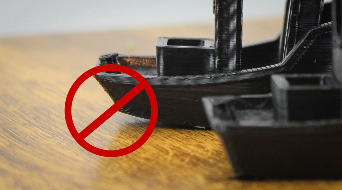
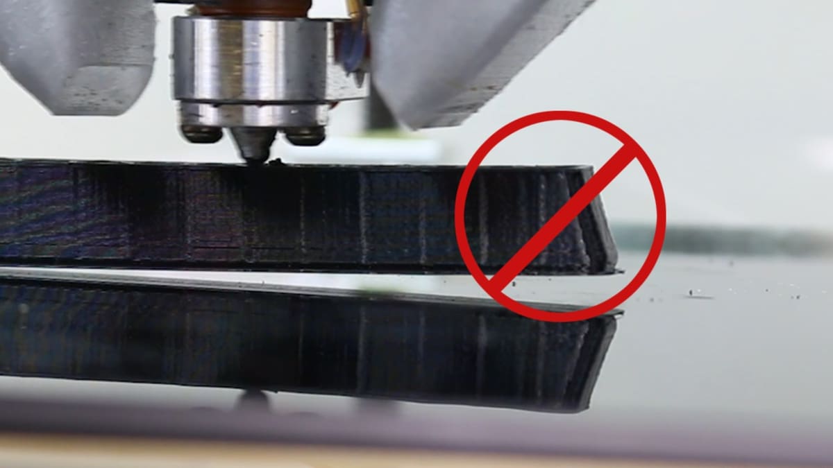
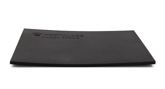
In 3D printing, warp happens when earlier layers of the print cool at a different rate compared to later layers. Material warp can result in both dimensional issues and aesthetic defects. When large cross-sections of material cool and contract, they can pull features out of their intended locations. You may see surface defects on parts where this occurs, and it can cause fitment or flatness issues if the warp is severe enough.
The truth is, in 3D printing all parts warp, it is just a matter of degree. The goal in part design is to mitigate this warp as much as possible and to the point that it does not negatively affect part accuracy or aesthetics.
The tips below apply not only to FDM printing but nearly all 3D printing processes. As such, designing a part to mitigate material warp also makes it much easier to transition to different materials and different 3D printing processes and still get a good part without redesign.
Design is not the only factor to consider in 3D printing when it comes to warp. The importance of heat, bed adhesion, and a host of slicer settings are covered in these All3DP guides below.


The Flipbook Thought Exercise
A good exercise is to visualize the print like a flipbook animation. Flipbooks create rudimentary animations on a pad of paper by changing the position of drawn characters from sheet to sheet. If your character doesn’t animate smoothly from one sheet to the next, it’s instantly noticeable and jarring. Building parts with 3D printing is kind of the same thing.
If your design doesn’t flow, or worse yet, jumps from layer to layer, your parts will run the risk of issues. So, if there are abrupt changes in the cross-section, your goal should be to make that transition more gradual with either a design change or a change in build orientation. The print should flow cleanly from layer to layer and be an organic flow of cross-sections. A part that flows smoothly throughout the build is an accurate and aesthetically pleasing part.
Fortunately, your slicer software preview can show you how your part will be built layer by layer. Pay close attention and note any jumps or gaps or harsh cross-sections.
Go for Organic Shapes

There’s a reason you see so many 3D parts in manufacturing take on an organic, tree-limb type of shape, instead of having hard corners and angles.
For many parts, adding radii (curves) to hard edges is the easiest way to reduce material warp. By adding a radius, the change in cross-section is made more gradually from layer to layer. Adding radii to interior edges is more effective than external edges, but if your design permits it can’t hurt to add radii to external edges, too. The radius can be quite small yet have an outsized impact. For example, a radius of 0.15 mm is enough to help relieve stress that builds in that edge. The larger the radius the better, until it starts significantly affecting the wall thickness. In general, the more the part resembles a melted candle the better in that melted candles organically form curves as they drip, rather than creating sharp breaks. It’s a more natural geometry. This is why we see so many parts optimized for 3D printing that look like tree limbs or cell structures, there aren’t a lot of hard angles in nature.
Breaking Angles & Uniform Wall Thickness
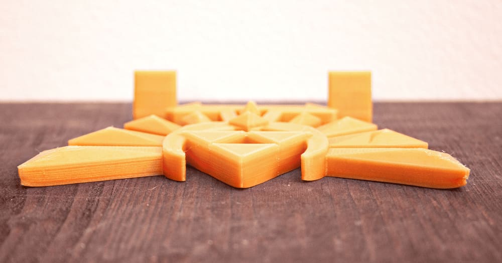
Hard 90-degree angles on parts typically result in drastic changes in cross-section, unless they are built at compound angles. Anywhere your design allows, consider breaking those 90-degree angles into two 45-degree angles, instead.
Another good practice for parts designed for 3D printing is to ensure uniform wall thickness as much as possible. If a part rapidly changes from thin-to-thick or thick-to-thin, it creates a large change in cross-section during the print and could result in material shrink. Some designs need thick and thin sections. In these cases, add radii or otherwise make the transitions as gradual as possible.
So, which wall thickness should you use? It varies by material, geometry, and printing process, but a good starting point is to make the wall thickness 1% of the part’s longest dimension. This means a 4-inch (101.6 mm) part is .040 in. (1.016 mm) thick and a 9-inch (228.6 mm) part is .090 in. (2.286 mm) thick. As you get under 3 inches (76.2 mm), you want to lean toward being a bit thicker and as you get over 10 inches (254 mm) go a bit thinner. If a design is more self-stable it can be thinner and if the design is fragile or not as stable, err on the side of being a bit thicker.
If a thick feature is required on the part, we recommend hollowing the feature to a shell of approximately 0.100 in. (2.54mm) to 0.125 in. (3.175mm). If possible, match the overall thickness of your part to the large feature’s shell thickness.
Rethink Build Orientation
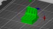
If a part cannot be redesigned to mitigate warpage, another factor to look at is orientation. Thinking about orientation should “bookend” your design process. This should happen in two stages. You want to plan around a build orientation at the beginning of your part design and rethink it again at the end. Often, the first orientation attempted is an orthogonal one, but many parts may build more accurately at a more compound angle. Consider a part that’s roughly shaped like the letter H and think through the flipbook animation thought exercise. When the part builds up to the center bridge, the material steps in all at once, pulling on the two legs below.
So how do you fix this? Adding a radius to the hard interior edges will make the transition more gradual and will alleviate, but likely not eliminate, the issue. So, more has to be done. What about tilting the H at a 45-degree angle? Now the bridge does not step in all at once and the transition will be much more gradual and organic.
For some parts, tilting at 45 may not be necessary. Even a 10- or 15-degree tilt can help. However, this can have a negative effect on layer lines or support requirements. The negative impact depends greatly on the 3D printing technology used. For example, selective laser sintering (SLS) or Multi Jet Fusion (MJF) don’t have scaffold supports and do not have significant stair-stepping from the layers, so this is a very common practice for those printing technologies.
Eric Utley is an applications engineer at Protolabs with more than 12 years of experience in rapid prototyping and additive manufacturing. He specializes in stereolithography, selective laser sintering, and direct metal laser melting technologies, and he provides guidance to engineers on designing for manufacturability.
License: The text of "3D Part Design to Eliminate Warp" by All3DP Pro is licensed under a Creative Commons Attribution 4.0 International License.