How to Design for Better Large-Scale 3D Printing

With the right guidance, anyone can use large-scale 3D printing to bring big ideas to life. Find all you need in this comprehensive and practical guide.
The first time I saw a large-scale 3D printer in action, I was hooked. The ability to design something and see it materialize just hours later is truly captivating. But what impressed me most was how this technology offers a balance between technical precision and creative freedom. It’s a tool that invites anyone, from designers to makers and problem-solvers, to explore new possibilities.
Yet, I’ve noticed that too often, the full potential of large-scale 3D printing goes unused because people don’t fully understand how to design for it.
It’s not as simple as scaling up from small desktop printers; it requires a completely different approach. Whether you’re a designer, a hobbyist, or just curious about the technology, the challenge is in marrying the technical with the creative to get the best results. For me, that means sharing as much knowledge as possible, understanding both the technical and creative sides, and bringing them together to make the most this technology.
That’s why I founded More Than Layers to make large-scale 3D printing accessible to everyone, regardless of their background. I want to help people — whether they’re designers, makers, or creators of any kind — realize what’s possible with this technology. With the right guidance, anyone can use large-scale 3D printing to bring big ideas to life, whether you’re making furniture, installations, or even artistic pieces.
This guide will take you through essential design tips for large-scale 3D printing, covering key aspects like choosing the right materials, optimizing print orientation, and fine-tuning your designs for the best results. You’ll find tips whether you’re exploring large-scale 3D printing for the first time or aiming to improve your existing workflow.
What is Large-Scale 3D Printing?
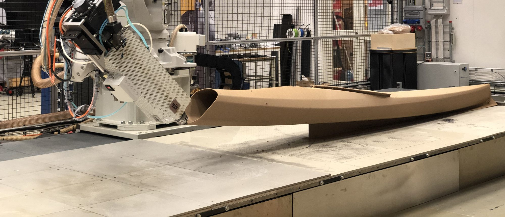
Large-scale 3D printing, often referred to as large format additive manufacturing (LFAM), involves systems capable of producing parts larger than 1 meter (three feet) in any dimension.
Although there are various technologies for producing parts on this scale, including fused deposition modeling (FDM), laser powder bed fusion (LPBF), wire arc additive manufacturing (WAAM), and some resin technologies, this guide focuses on robotic arm extrusion-based methods that are used for large-scale projects in industries such as construction, automotive, furniture, and art. These printers do not use standard slicing software and instead have their own distinct toolpath generating systems.
Robotic arm 3D printers differ greatly from desktop 3D printers, not only in size but also in technical complexity, material handling, and overall workflow. In fact, it’s a common misconception that parts and models can be simply scaled up for LFMA. It’s like being a home cook vs. being a restaurant chef: your equipment, materials, and processes need to be completely different.
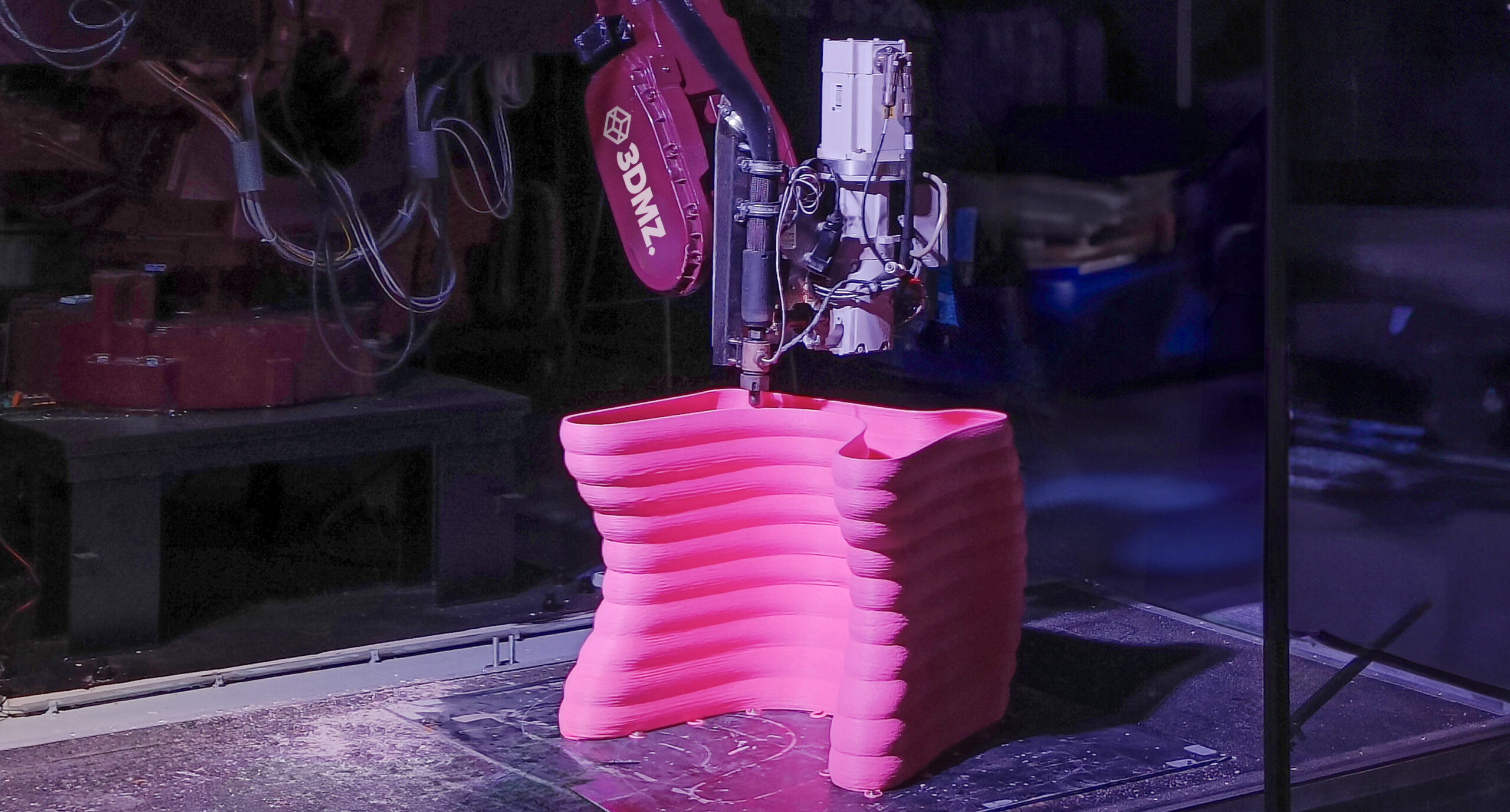
The rapid rise of LFAM is driven by both technological advancements and market demand. Modern large-format printers handle a variety of materials beyond standard thermoplastics, including concrete, composites, and fiber-reinforced plastics. The ability to create larger, functional parts at scale has opened up new possibilities for applications, offering speed, customization, and sustainable solutions in sectors ranging from architecture to manufacturing. Projects like custom architectural structures and automotive prototypes are just the beginning of what LFAM can achieve.
Although the machines, materials, and software have advanced, one hurdle to wider application of LFAM is how to design parts for it. Here, I’ll guide you through essential design strategies, material selection, and workflow optimization, offering practical guidance to designers transitioning from small-scale to large-format printing.
Applications of Large-Scale 3D Printing
Large-scale 3D printing has broad applications across various industries, including construction, automotive, and art. Here are some recent examples:
Automotive
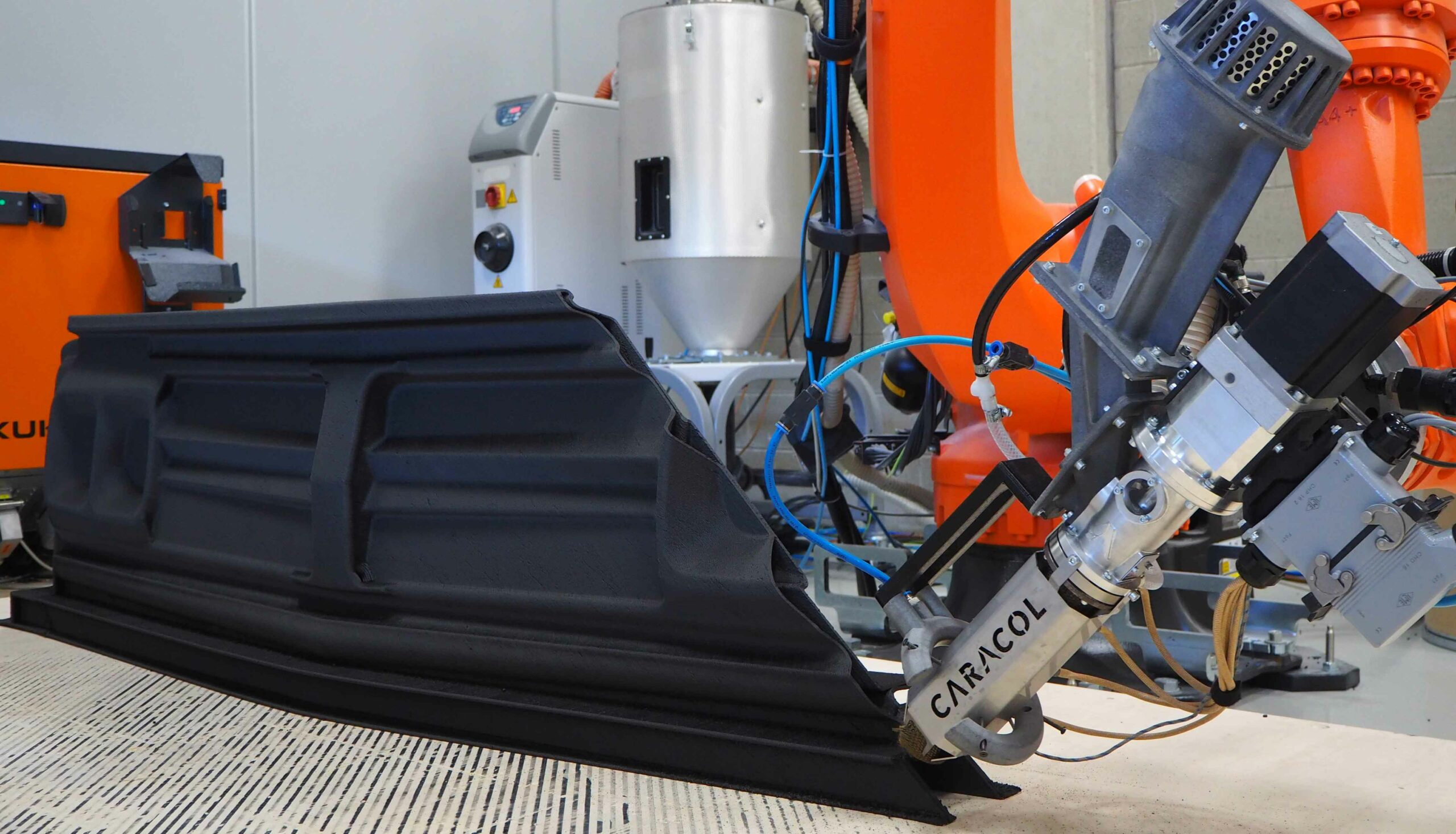
Last year, 3D printer maker Caracol AM manufactured a 1,900 x 300 x 500 mm front grille mockup of a 1968 Chevrolet C10. The prototype was printed in a single piece with Caracol’s Heron AM 300 robotic arm 3D printer and took 10 hours, which was a 70% savings in time and a 60% cost savings compared to traditional manufacturing methods, according to Caracol.
Construction
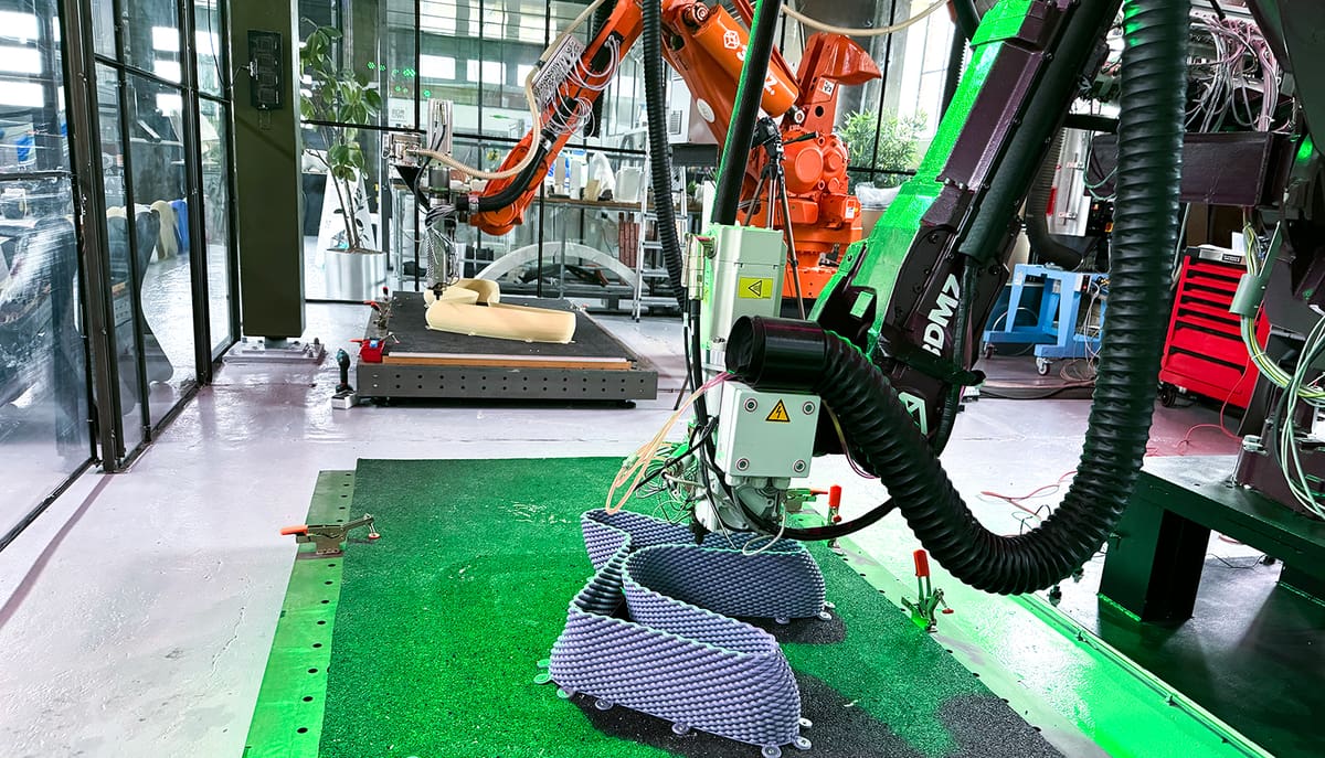
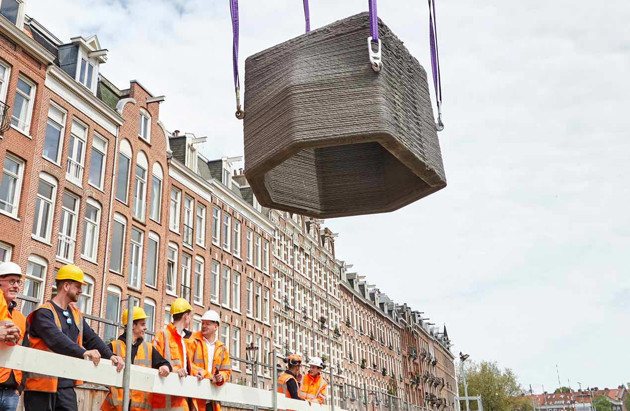
Large format additive manufacturing in the construction industry, more commonly known as construction 3D printing, is being used to produce the walls and internal features of homes and buildings, plus custom architectural and structural elements. Dutch company Neolithic 3D, specialized in sustainable objects in concrete, stone, and clay, printed the water wells above for a construction project in Amsterdam.
Art and Architecture
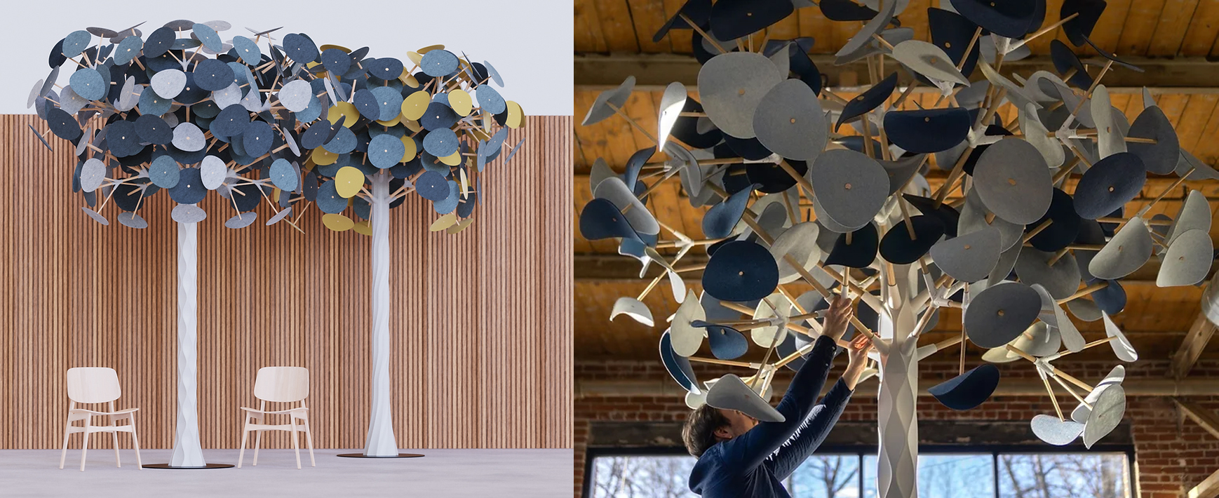
LFAM is revolutionizing the world of art and design, enabling the creation of complex, large-scale sculptures and functional furniture. Recently a company called Willo Furniture designed indoor, sound dampening 3D printed trees made in the US from recycled materials.
Design & Furniture
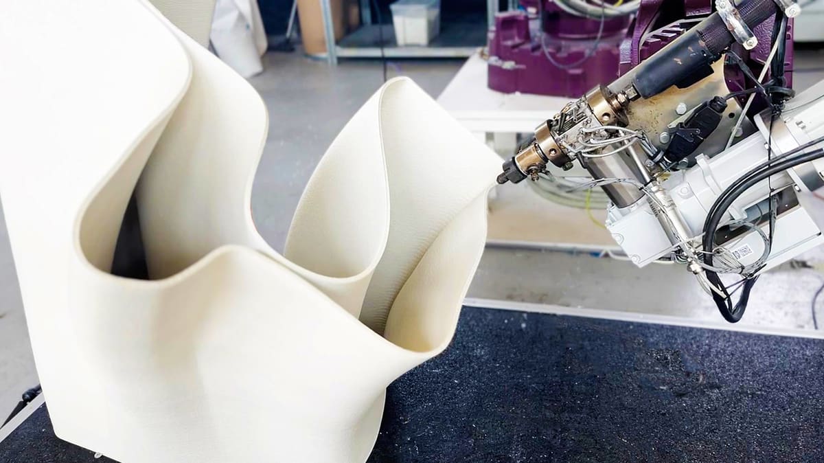
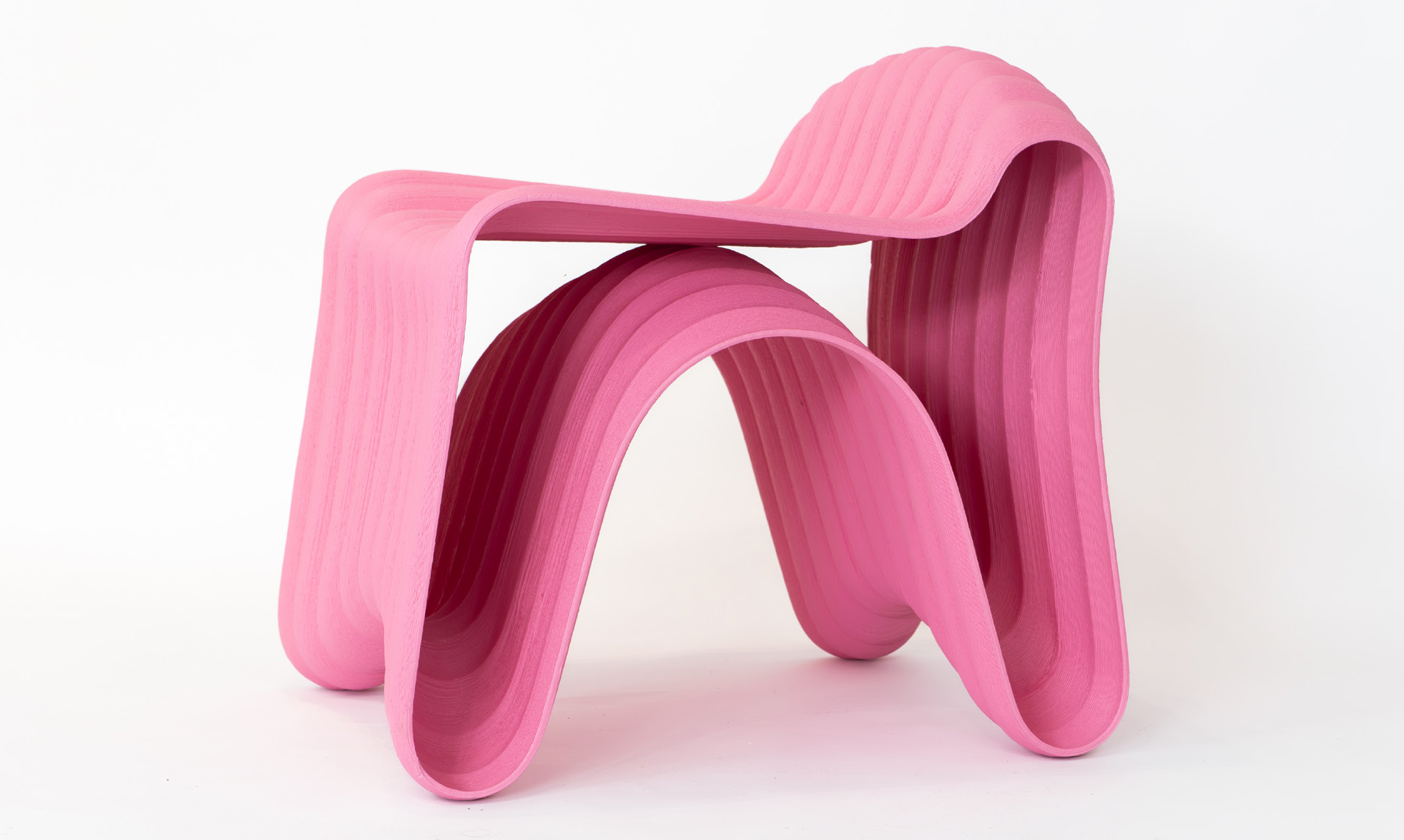
On the creative side of LFAM, furniture is one of the most popular applications. Chairs, stools, tables and lamps are now becoming almost commonplace. This example above — our own Bobble chair — demonstrate the power of large-scale printing to merge aesthetic appeal with structural integrity.
The 10 Most Important Considerations in LFAM

Now that you’ve seen a few examples of the broad application on large format 3D printing, it’s time to take a look at how it’s done, which all starts with the design.
If you’re already somewhat familiar with designing for desktop-size 3D printing, the first step in moving up to large format is to forget most of what you know. Large scale require a shift in mindset and placing a greater importance on your material selection and your print orientation, to name just a few critical areas.
Below are probably the top 10 ways that designing for large scale is different from designing for small scale and why they’re important.
Design with Nozzle Size in Mind
Nozzle size plays a critical role in determining the overall quality and strength of a large-format print. When designing, it’s helpful to consider the nozzle diameter and create wall thicknesses in multiples of that size (e.g., if you’re using a 2 mm nozzle, wall thicknesses should be 4 mm, 6 mm, or 8 mm). Nozzle sizes can vary a lot in LFAM, from 2 mm up to 24 mm. Additionally, ensure that features meant to sit close to each other are nearly touching but not overlapping to avoid material buildup. Planning your design with nozzle size in mind leads to stronger and cleaner prints with fewer technical issues.
Master Adaptive Layer Heights & Print Speeds
Balancing print speed with detail is crucial when designing for large-scale printing. Larger layer heights (4 mm) significantly reduce print time but may sacrifice fine detail, resulting in a rougher surface or a part that is designed to require post-print milling. On the other hand, smaller layer heights (1-2 mm) offer finer detail but considerably extend print time. One approach is to use adaptive layer heights, where larger layers are applied in areas with less detail, and smaller layers are used in intricate sections. This technique allows you to speed up the process without compromising on quality where it matters most.
Steer Clear of Materials that Warp
Large-scale printing requires robust materials, especially when producing functional or structural parts. Reinforced materials, like glass-fiber-infused polymers, offer the necessary strength and stability, preventing issues like bending or warping. For non-structural components or prototypes, standard materials like PLA may suffice, but can be very brittle. Sustainability should always be considered, so choose recycled, recyclable, or eco-friendly materials where possible.
Simple Supports May Not Be Enough
When scaling up a design for LFAM, the structure must support significantly more weight than it would at a smaller scale. Walls that worked fine on a small printer might buckle under the added pressure of a large print. A good rule of thumb is to aim for a wall thickness of at least 5 – 10 mm, depending on the material. You can also incorporate ribs and gussets to strengthen areas without adding too much weight.
Rethink Your Print Orientation
Orientation is even more critical in LFAM than in small-scale 3D printing, as large prints often require more support structures. Minimizing overhangs and strategically rotating your model can reduce the need for supports, which consume both time and material. Keep overhang angles under 45 degrees and design self-supporting features, such as chamfers, to streamline the print and minimize post-processing.
Robotic arm 3D printers and variable angle print beds may also enable you to start printing in one direction then adjust to another angle.
Design Differently for Faster Post-Processing
In LFAM, support structures must be designed to be both strong and easy to remove. Use lattice-like supports that hold up the part effectively but are also lightweight. Make sure supports are strategically placed to be easily accessible for removal without damaging the printed object. This is especially important in large prints, where manual removal can become time-consuming and labor-intensive. Yet, ultimately, the best designs don’t require support structures or they are incorporated into the design.
Watch Out For Heating and Cooling Pitfalls
Large-scale prints are more prone to warping due to uneven cooling. The larger the object, the more critical it is to maintain consistent thermal conditions throughout the process. Avoid large flat surfaces in your design and aim for uniform wall thickness to reduce thermal stress. Printing in a heated chamber can also help maintain a consistent temperature and prevent cooling-related distortions. To improve adhesion, use a heated bed and apply adhesive sprays, tapes, or textured surfaces to the build plate. For larger prints, adding a brim or raft can also help by increasing the contact area with the bed, reducing the risk of lifting.
CAD Software Struggles with Large Format
Designers must also be mindful of equipment limitations. Standard desktop CAD software may struggle to handle large-scale designs. Instead, advanced tools like Autodesk Fusion 360 and Rhino can handle large, complex geometries and prepare them for printing. When a design exceeds the printer’s build volume, it’s crucial to segment the model into smaller pieces that can be assembled post-printing without compromising the overall structure.
Stop Tiny Imperfections From Becoming Huge Flaws
Minor errors in small-scale prints can become major issues in LFAM. Tolerances must be increased slightly (by 0.5-1 mm) to account for potential variations in material behavior and machine accuracy. Regular calibration of the printer is critical, especially for long-duration prints. Failing to account for slight shifts in the material or toolpath can result in parts that don’t fit together or require excessive post-processing to align. If tight tolerances are required, plan your design around 3D printing and milling.
Assembly Is Not a Failure: Embrace Modular Design
Most large-format prints cannot be created in a single piece due to the size constraints of the printer. Instead, the design should be broken down into modular parts that can be printed separately and later assembled. Incorporating features like alignment pins or dovetail joints ensures that the parts fit together precisely, making post-print assembly straightforward. Modular design also makes transportation and handling easier, especially for very large components.
Top Design Strategies for Large Scale 3D Printing

In the last section, you learned the major principles, so now let’s drill a little deeper in to actual strategies. These are the design practices that successful companies follow to ensure optimal prints.
Not every strategy applies to every print, but if you master incorporating these into your designs, you’ll have more reliable and functional final products.
Think in Toolpaths Not Slices
In LFAM, your design isn’t just about the final shape—it’s about how the machine will build that shape. This is a change in mindset from smaller FDM 3D printing. Focus on continuous toolpaths to reduce start-stop points, avoid defects, and improve print quality. Large-scale prints that involve many start-stop points can suffer from weak spots or visible defects. One way to avoid these issues is to design with continuous toolpaths in mind. Plan your design so that the printer can move in a smooth, uninterrupted path, minimizing the number of times the print needs to pause and restart. Fillets and rounded corners help maintain this flow, reducing defects and improving overall surface quality.
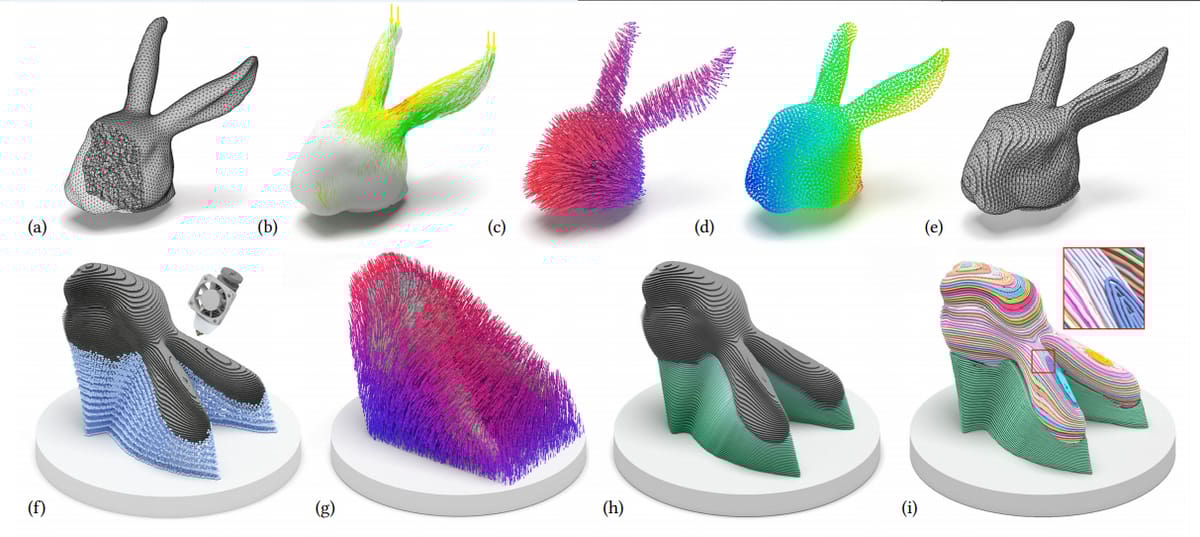
Topological Optimization Is More Critical
One of the key challenges in LFAM is keeping parts strong without making them too heavy or using excessive material. Topological optimization is a design technique that allows you to remove unnecessary material while maintaining structural integrity. This approach results in more efficient, organic shapes that are lighter, use less material, and reduce printing time. By incorporating this into your design workflow, you ensure that the final print is both functional and cost-effective.
Designing for Flexibility in the Right Way
Creating flexible features in large-scale prints can be tricky, especially when using materials that are inherently rigid. To add flexibility, consider using flexible materials like TPU for specific sections or introducing living hinges or thin-walled sections. These features enable certain parts to bend or flex while maintaining the overall structural integrity of the design. This is especially useful in applications such as furniture, where comfort and usability may require a degree of flexibility.
Rethink Your Infill Strategy for Better Internal Structures
Instead of using traditional infill patterns (which are often wasteful), consider designing with internal ribs or lattice structures. These provide support only where it’s needed, reinforcing critical areas without overusing material. This strategy is particularly effective in large prints, where the internal structure can have a significant impact on both strength and print time. Internal ribs allow you to reinforce specific stress points while keeping the design lightweight and efficient.
Test small sections of your large designs before committing to full-scale prints. This can help identify potential issues with structural integrity, material shrinkage, or warping, and allow you to make adjustments early in the design process.
Consider Hybrid Manufacturing (3D Print / CNC) For Best Results
LFAM often requires extensive post-processing to achieve a high-quality finish. Hybrid manufacturing setups, where milling is combined with printing, can streamline this process. In software like AI-Build and Adaxis, the toolpath can be designed with both additive and subtractive steps in mind. To prepare for milling, add extra material (around 2-4 mm) in areas that will be machined afterward, ensuring that post-processing has enough material to work with without compromising the final dimensions of the part.
Software For Generating LFAM Toolpaths
In LFAM there is no slicing software, rather toolpath software that generates the G-code or the language used to control and guide the 3D printer.
G-code for a robotic arm 3D printing is different from standard FDM G-code because robotic arms have multiple degrees of freedom, meaning they can move and rotate in ways that traditional FDM printers can’t. This added flexibility allows the tool orientation to change during printing, letting the nozzle approach the part from different angles. As a result, the G-code must include commands to control these movements, ensuring the tool stays aligned with the desired path.
Another big difference is how layer heights are handled. In FDM, layer heights are usually (but now always) fixed, but with robotic arms, you can use adaptive layer heights, where the layer thickness changes depending on the part’s geometry. This means the G-code needs to adjust the extrusion values dynamically, matching the amount of material to the varying layer heights. This flexibility helps optimize material use and print quality, but it also means the G-code is more complex, as it has to account for these continuous adjustments in real-time.
Fortunately there’s specialized software that automatically creates toolpaths and the accompanying G-code from imported digital design files.
Software companies, including Adaxis and AI Build, offer programs that are ideal for designers who want to focus on design and let the software handle the technical aspects of toolpath creation.
- Benefits: Speed and efficiency, with advanced features like non-planar slicing and dynamic flow control.
- Drawbacks: Less control over fine details; the software may simplify toolpaths, potentially missing intricate design elements.
- When to Use: Great for rapid, functional prints that prioritize efficiency over detailed customization.
Other software used to generate G-code for 3D printing digital design files include computer-aided manufacturing (CAM) tools that support complex multi-axis robotic movements. These are suitable for users who require more detailed control over the robotic arm’s behavior in a broad range of applications, not just 3D printing.
- SprutCAM is a versatile CAM software that’s particularly useful for robotic 3D printing because it allows for detailed control over toolpaths, including multi-axis movements. SprutCAM can handle complex geometries and offers extensive simulation capabilities to ensure that the robotic arm’s movements are optimized and collision-free.
- RoboDK is a powerful simulation and offline programming tool that supports a wide range of robotic brands. It’s well-suited for robotic 3D printing with capabilities to generate toolpaths that consider the full range of motion of the robotic arm. RoboDK is known for its flexibility, enabling you to import G-code or create custom paths while simulating the entire process to check for potential issues.
- Siemens NX is a high-end, integrated solution that includes advanced tools for additive manufacturing, including robotic 3D printing. It supports multi-axis toolpaths and can simulate the entire printing process within the same environment. Siemens NX is particularly strong in handling the complex requirements of industrial-scale production, making it a robust option for those looking to integrate robotic arms into larger manufacturing workflows.
- Octopuz is another CAM software designed specifically for robotic arms, with a focus on multi-axis control and complex path planning. It supports a wide variety of robotic brands and can handle multiple robots working in tandem. Octopuz is known for its user-friendly interface and strong simulation capabilities, making it a solid choice for those looking to integrate robotics into their additive manufacturing processes.
- Autodesk PowerMill is typically used for CNC machining, but it also has powerful capabilities for robotic programming, including 3D printing. PowerMill can create precise toolpaths for multi-axis robots, offering advanced control over every aspect of the print. It’s particularly useful when high precision and complex geometries are involved.
- Robotmaster is an offline programming software that simplifies the process of creating complex robotic paths. It integrates well with various robotic brands and is known for its ease of use. Robotmaster allows you to take advantage of the full range of motion of a robotic arm, making it a strong option for additive manufacturing tasks that require detailed toolpath control.
Although these software products are broadening the access to large format 3D printing to designers by simplifying the process, there is another way some designers prefer that gives them more fine detail control over the 3D printer.
You might find that automatic toolpaths don’t always capture the nuances of your design, especially if it’s highly specialized or unconventional. The software’s optimization algorithms are powerful, but they can sometimes oversimplify the path, leading to compromises in the final product. Additionally, because the process relies heavily on the software’s capabilities, you might run into issues if the program isn’t up to date or doesn’t support certain features needed for your project.
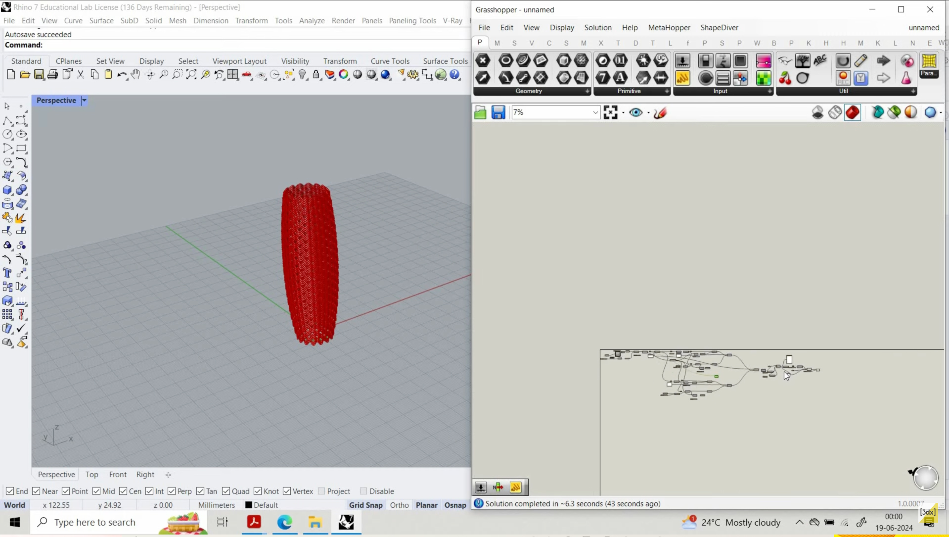
Custom Toolpath Design (Rhino + Grasshopper)
For more advanced projects, designers may choose to create custom toolpaths in software like Rhino + Grasshopper, giving them complete control over machine movements.
Here, you create the path directly within the design environment, adjusting the movements of the printer to match your exact specifications. This approach is all about precision and customization, giving you the freedom to craft the print exactly as you envision it.
- Benefits: Full customization of every detail, allowing designers to control every movement of the robotic arm.
- Drawbacks: Time-consuming and requires technical expertise in G-code and machine operation.
- When to Use: Ideal for complex designs, such as artistic pieces or furniture like the Booble chair pictured above, where I found that the automatic toolpath generation didn’t provide enough flexibility.
The main benefit of manually designing your toolpaths is control and the ability to tailor the toolpath to the specific needs of your design, whether that’s for intricate details, unique material properties, or unconventional shapes. This method is ideal for complex, artistic, or highly specialized projects where the standard toolpaths generated by software might fall short. Plus, it opens up space for innovation—allowing you to experiment with new techniques and push the boundaries of what’s possible in LFAM.
But with greater control comes greater complexity. Manually designing toolpaths requires a deep understanding of both the software and the printing process, making it less accessible to beginners. It’s also more time-consuming—what an automated toolpath might handle in minutes could take hours to design by hand, especially for large or detailed prints. Additionally, the risk of error is higher since there are fewer automatic safeguards to catch inefficiencies or mistakes in the path.
In the end, although automated tools like Adaxis are faster and more user-friendly, making them ideal for larger prints where the focus is on function. Custom toolpaths, on the other hand, provide maximum flexibility for intricate designs but require a higher skill level.
Simple, functional prints can benefit from automated toolpaths, while complex projects (with unique geometries or artistic elements) require the precision that custom paths offer.
Ultimately, the choice between these two methods depends on the specifics of your project. If you need speed, efficiency, and ease of use, importing files into automated toolpath software is the way to go. However, if your project demands precision, customization, and the ability to innovate, taking the time to design your toolpaths manually might be the better choice. Both approaches have their place in LFAM, and knowing when to use each is key to maximizing your success in large-scale 3D printing.
Understanding both methods and how to leverage their strengths can give you a significant edge in LFAM. Mastering automated toolpaths can streamline your workflow, while expertise in manual toolpath design can open up new possibilities for complex and creative projects. Balancing these approaches will allow you to tackle any design challenge that comes your way.
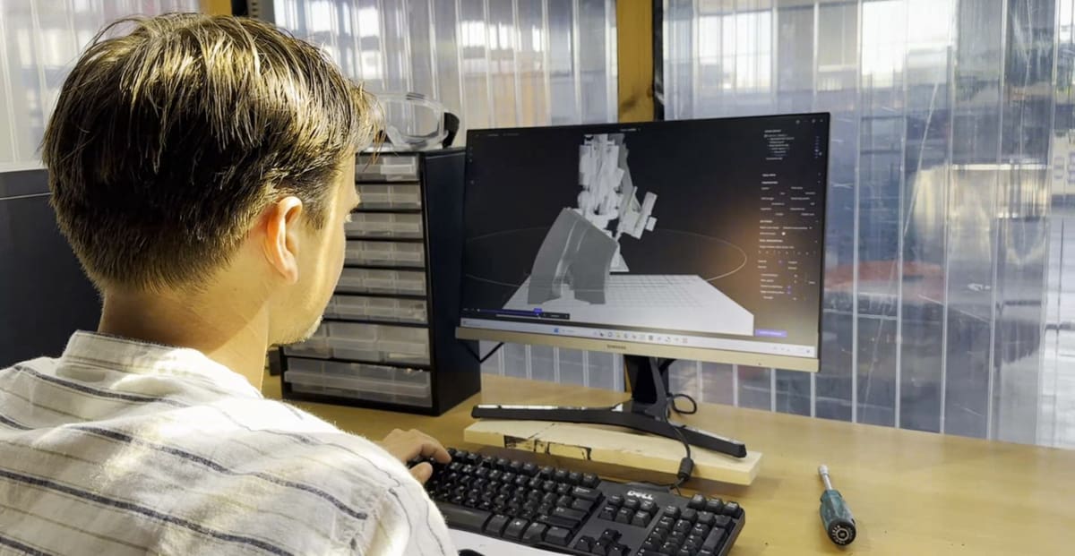
Integrating with Robotic Arm Software
Unlike slicing software that integrated directly with desktop FDM 3D printers, large format 3D printing with robotic arm systems have an extra layer of software.
Once the G-code is generated, it needs to be transferred into robotic arm control software, such as RobotStudio for ABB arms or KUKA.CNC for KUKA robots. This software enables you to simulate the print, ensuring there are no collisions or mechanical issues during printing. Before starting the print, run a simulation to check for potential issues with tool orientation or reach.
Selecting the Right Toolpath for Your Part
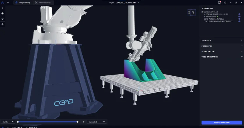
When you import a CAD file, such as a STEP or FBX, into software like Adaxis or AI-Build, the program automatically generates the toolpath based on the geometry you’ve designed. These tools are built to optimize the path for efficiency, often adjusting for speed, material use, and even machine-specific settings. The software handles the heavy lifting, creating a toolpath that should work well for most projects.
However, with some software you do have toolpath options to choose from and you should know the differences between these slicing plans.
Slicing Strategies
- Planar Slicing. This is the most common slicing method where the model is sliced into flat, horizontal layers. It’s straightforward and works well for most simple designs. You’d use planar slicing for basic shapes or when speed and simplicity are your main goals.
- Multi-Planar Slicing. This method involves slicing the model into layers that aren’t strictly horizontal. Instead, the layers can be tilted or angled to better match the geometry of the part. Use multi-planar slicing when your design has complex angles or features that would benefit from being printed in a direction other than flat. It can reduce the need for supports and improve the strength of the final part.
- Surface Interpolation. This technique creates toolpaths that closely follow the surface of the model, even if it’s curved or irregular. Instead of sticking to a rigid layer height, the toolpath adapts to the shape of the model’s surface. You’d use surface interpolation for parts with intricate or organic surfaces where you want a smooth finish without the stepping effect that can occur with traditional slicing.
- Cladding. Cladding involves adding extra material to the outer surface of a part, usually for reinforcement or to create a specific surface texture. This strategy is useful when you need to strengthen the exterior of your design or give it a more durable or aesthetic finish. It’s often used in situations where the outer layer of the part needs to be tougher or where you want to apply a particular surface pattern.
- Non-Planar Substrates. This slicing strategy is used when the base or substrate on which you’re printing isn’t flat. The toolpath adapts to follow the contours of the non-planar base, allowing you to print on surfaces that are curved or irregular. You’d use this technique when you’re printing onto an existing part that isn’t flat, like when adding a new layer to a curved object.
- Angled Slicing. Angled slicing involves slicing the model at a specific angle rather than horizontally. This can help in reducing supports or improving the strength of the part in certain directions. Use angled slicing when your design has features that benefit from being printed at an angle, like overhangs or inclined surfaces that would otherwise need a lot of support material.
Combining Multiple Strategies
Sometimes, a single slicing strategy isn’t enough to achieve the best result, so you combine several methods. For example, you might use planar slicing for the main body of the part, surface interpolation for intricate details, and cladding for a reinforced exterior. Combining strategies allows you to tailor the printing process to each part of your design, improving overall quality, strength, and efficiency.
Sustainability in Large-Scale Design + Materials
One of the attractive elements of large format 3D printing is its ability to 3D print with plastic waste and recycled materials. There are several examples of campaigns to turn waste into desirable products via 3D printing. Coca Cola worked with a town in Greece to recycle plastic bottles into beach furniture, Japan collected plastic waste to fashion the winners’ podiums for the 2020 Olympics, and packaging company Tetra Pak collaborated with 3D printing company Aectual to craft furniture from drink cartons.
Robotic arm 3D prints typically do not 3D print with filament rather opting for pellet material or recycled plastic shreds.
Choose materials that are recyclable or bio-based to minimize waste. Use design techniques like topological optimization to reduce the amount of material needed and create structures that are efficient and environmentally friendly.
As large-scale 3D printing grows, sustainability becomes an important factor, especially due to the amount of material involved in producing larger objects. Here are a few key ways designers can integrate sustainability into their workflow.
Material Selection
Designing with sustainability in mind starts with choosing the right material. For LFAM, options like recycled thermoplastics or bio-based composites can help reduce the environmental impact. Beon3D, for example, offers a recyclable polypropylene material that balances durability with environmental responsibility, making it a great choice for large-scale prints. Selecting materials with a lower environmental footprint helps to reduce waste, and many materials used in LFAM can be recycled or repurposed after their lifecycle.
Designing for Minimal Waste
One of the key ways designers can minimize waste is by optimizing the design itself. Using topological optimization, you can reduce the amount of material needed by only placing material where it’s structurally necessary. This helps to create parts that are strong, lightweight, and efficient to print. Additionally, design parts with self-supporting features where possible to minimize the need for wasteful support structures.
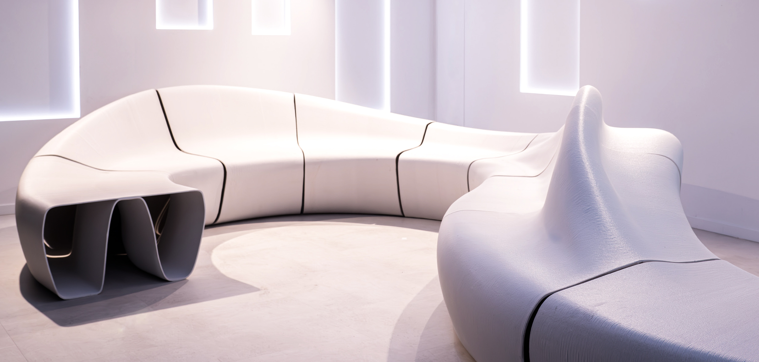
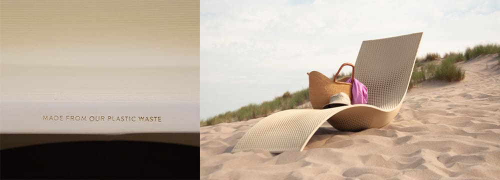
Closed-Loop Manufacturing
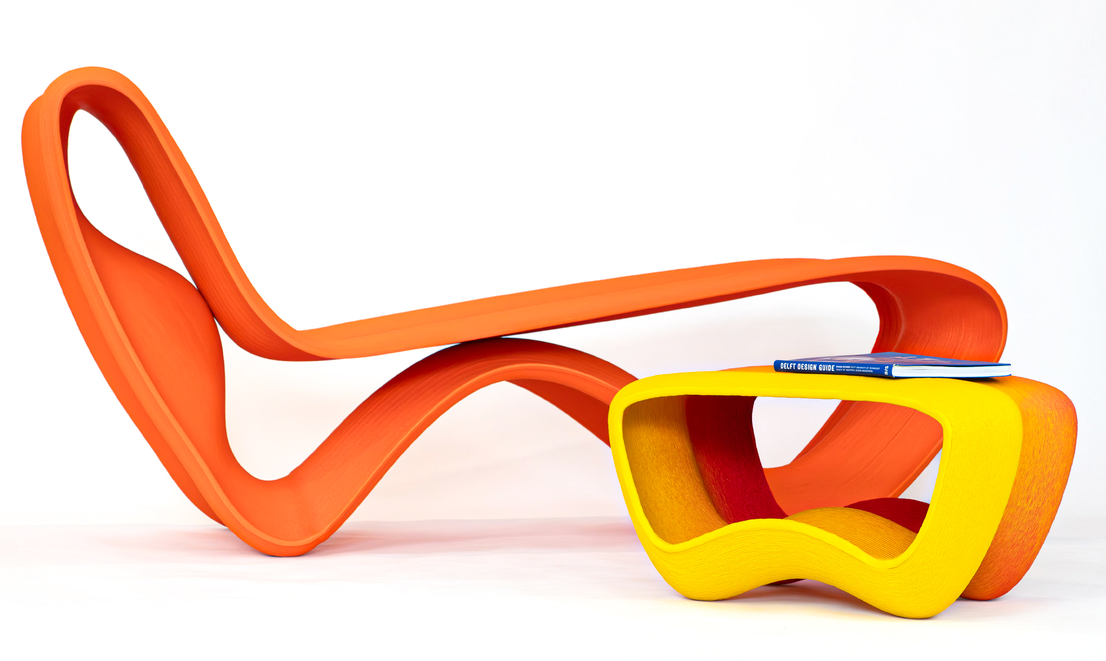
Consider designing with a closed-loop system in mind, meaning that the materials used in the print can be reused or repurposed. In projects like the Model.C3 lounge piece (pictured above), materials were chosen not only for their mechanical properties but also for their ability to be recycled and reintegrated into future production cycles. This approach supports a circular economy, where materials can be used again and again, reducing overall environmental impact.
Energy Efficiency
The energy consumed during large-scale printing can be significant. To reduce this, design with efficiency in mind by minimizing print times and optimizing the toolpath to reduce unnecessary movements. Choosing energy-efficient materials and printing in environments with stable temperatures can also help lower the overall energy consumption of the print process.
Post-Processing & Hybrid Manufacturing Strategies

In large-scale 3D printing, the need for post-processing is almost always greater than with small-scale prints. Post-processing in LFAM typically involves sanding, milling, and finishing, and hybrid manufacturing approaches can streamline this process.
Designing with Milling in Mind
One key consideration is designing parts that can be milled after printing. Hybrid systems, such as those integrated into AI-Build and Adaxis, combine both additive and subtractive processes. To account for milling, add extra material in areas that will need to be machined later—typically around 1-2 mm thicker than the final dimensions. This ensures that there’s enough material to work with when achieving a smooth surface or specific fit.
Surface Quality
If surface quality is a concern, plan for additional post-processing steps during the design phase. For example, large flat surfaces may need to be machined for a smoother finish, while curved or intricate features might require sanding or polishing. Adding extra thickness in these areas during the design stage will give you more control during post-processing, leading to a higher-quality final product.
Combining Additive and Subtractive Manufacturing
In hybrid systems, printing and milling are performed together to create a part with high precision and excellent surface finish. This is particularly useful in industries such as automotive and architecture, where both strength and aesthetics are key. When designing for hybrid manufacturing, consider how the part will transition between the two processes—ensure that the toolpaths for both printing and milling are carefully aligned to avoid errors.
Large-Scale 3D Printing Post-Processing Techniques
- Sanding: To remove surface imperfections or layer lines, making the print smooth and ready for finishing.
- Machining: Using milling or other subtractive methods to refine the final dimensions and surface quality.
- Coating or Painting: Applying a finish to enhance appearance or protect the part from environmental conditions.
About the Author
Michael John Sweers, founder of More Than Layers, brings over a decade of experience in Design for Additive Manufacturing (DfAM), with a focus on Large Format Additive Manufacturing (LFAM). Through More Than Layers, he democratises LFAM by providing creative professionals with the tools, knowledge, and support to turn their ideas into functional designs from the start.
License: The text of "How to Design for Better Large-Scale 3D Printing" by All3DP Pro is licensed under a Creative Commons Attribution 4.0 International License.