How to Prep Architecture Models for 3D Printing

If prepping your architectural model files for the 3D printer is more complex than you thought, learn these ins and outs of file prep for flawless 3D printed models.
Architects have been rapid prototypers long before rapid prototyping existed. They’ve been iterating their designs with foam, cardboard, wood and – maybe not so rapidly – through casting. Architects gradually made the shift to generating their designs in 3D printing about the same timeline that 3D software moved into mainstream commercial use.
It would have seemed like an obvious evolution for architects to adopt 3D printing. In doing so they would continue to develop their designs seamlessly through prototyping in a more digitally connected workplace.
However, 3D printing isn’t yet a ubiquitous tool across the architectural sector. Why?
Model for Manufacture
In industries where additive manufacturing is more prevalent, such as automotive or medical, parts are designed specifically for manufacture with 3D printing in mind and importantly at 1:1 scale. Architectural files, on the other hand, are mostly modeled for communication, not for manufacture.
The majority of architectural 3D printing is still an afterthought. Digital models for communication lack the precision of engineered parts and likewise they’re almost always dynamic works-in-progress. At the stages when architects typically need models most, their file is also essentially the equivalent of a sketch.
Rethinking the architectural design process to fully incorporate 3D printing demands an entirely new skillset, which has prevented a lot of architects from adopting 3D printing in-house, especially true for those who work at smaller, resource-restricted firms. Although many architecture firms have committed to embracing and integrating 3D printing into their design and communication workflows, and are subsequently reaping all the benefits, there are many more who have been turned away by the problems that arise from the disconnect between architectural files and 3D printable files.
In this article, we’ll guide you, step-by-step through two approaches for printing fantastic architecture 3D models from your architecture design files.
Two Ways To Prep Your Architecture for 3D Print
Overcoming these issues to prepare an architectural file for 3D printing can be approached in two ways – both routes have their merits and their potential pitfalls:
1. Modeling for Manufacture: This is building a 3D printable model from scratch, referencing the architect’s design file.
Positives
- Modeling is done with the end objective in mind
- Full control (and artistic license) over the files creation
Negatives
- Starting from scratch (might not fit project timeline)
- Design might change in the meantime, making the work obsolete
2. Reverse Engineering (fixing): This is adjusting the architect’s design file to make a 3D printable file.
Positives
- Can be faster depending on the quality of the data and the skill of the 3D print technician/‘fixer’.
- Architect/Initial file creator doesn’t need any 3D Printing knowledge and doesn’t need to concern themselves with these details.
Negatives
- The knock-on effect of the file not being created with 3D printing in mind is that there are a lot of unknowns which can increase communication required between fixer and designer.
- On a very rare occasion no fix is possible
Preparing the file from scratch for manufacture is often the approach that is taken internally by the architectural design team, while reverse engineering the file would more likely be outsourced either to a different department or a specialist.
In both cases, expert 3D printing knowledge is required somewhere along the production chain. Your choice will most likely depend on your own resource and circumstances. Generally, a hybrid approach brings the most efficiency. This would involve the designer being aware of what a 3D printable file must do (more on this shortly) and taking care while modeling to meet those parameters. This will then reduce the unknowns and any potential time sink involved in the fixing process.
No matter which file preparation path you choose, you need to have a clear understanding of the following as they will all influence the approach to preparing the model.
What is the objective of the model?
Is it for internal use or for external client meetings, to show an internal space or the effect of the building on its surroundings? This will drive later choices and most of the model details.
What scale/size of model are you looking to produce?
The larger the model, the more time it will need to print and will also likely need to be produced in multiple parts (the joints of which might then need to be concealed).
What technology do you intend to use?
Choice of technology will introduce further size, time and finish constraints, as well as different post-processing methods.
What are your deadline, budget, and technical resources?
Often ambitions will need to be checked to ensure that they’re achievable and feasible within commercial constraints.
Modeling for Manufacture from the Ground Up
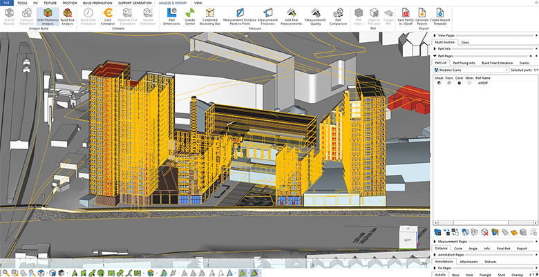
To design effectively for architectural 3D printing you need to understand the inherent qualities necessary in a 3D printable file. These are independent of whether they’re architectural files or not. All CAD software packages export STL files, but whether they’re 3D printable is a very different matter.
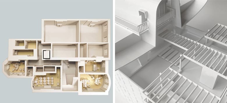
Each individual part you 3D print needs to be a closed shell of a suitable wall thickness (relevant to the technology). Whether your entire model is printed as one or you have multiple stackable floors or perhaps buildings separated from the landscape; each will need to be a shell in and of itself. Issues generally arise when that shell isn’t closed (has holes), shells/surfaces are overlapping, there are remnants or artefacts of geometry within the shell walls, or normals are inverted (back faces are showing).
If you are aware of these issues in advance, then the software you choose can simply be the modeling software that you have most command over and feel most comfortable with. What makes most architectural software difficult from a 3D printing standpoint is the multiple individual components (that are rarely modeled to be touching exactly) the high level of detail (fixtures and fittings with information down to the screw) and the lack of accuracy (components can overlap and intersect without impacting the architects’ objectives). However all of these characteristics slow down the process and are of course not necessary in a 3D printable file.
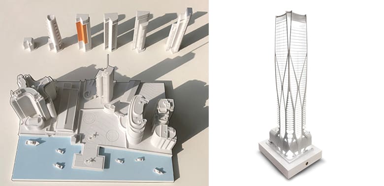
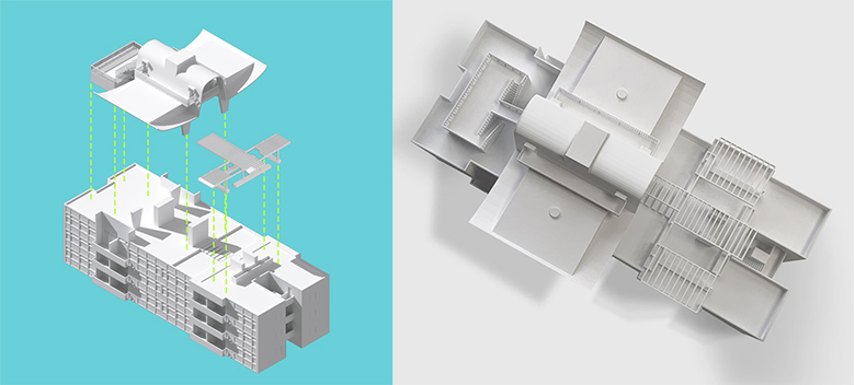
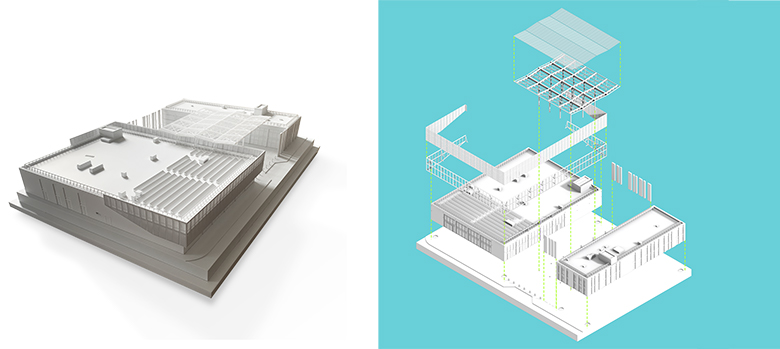
Some people like to model the entire model as one shell from scratch (roof connected to walls, connected to mullions, connected to window panes). While this makes sure you don’t miss any possible issues, it can be more time consuming. A second approach is to model elements individually (ensuring they’re touching) and then merge/unify/boolean depending on your software’s terminology into a single shell at the end of the process.
Architectural models can be beautifully detailed 3D prints, it is the joy of working in this sector of 3D printing, however sometimes you can get lost in the detail you are seeing on screen. Don’t be afraid to thicken elements to such a point that on your screen they may almost look comical, but in reality those 1 mm thick balustrades aren’t all that out of place on a printed model. Keep in mind, models are representations and while 3D printing offers the ability for exact reproduction of the digital model, sometimes (due to architectural models being produced to a fraction of their intended real world size) features will need to be manipulated – thickened and/reduced in frequency (e.g. removing every second louvre or railing) or totally removed (e.g. balcony glazing). The result will be a happy medium between 3D printability and design intention.
Reverse Engineering or Fixing your Existing CAD Model
In this file prep option, you have a full, final architecture design CAD file. This file was created with digital presentation in mind and now you have to convert it to be 3D printable.
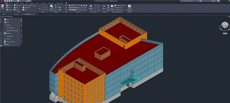
For this step, you’re going to need additional software for 3D printing file preparation, such as Magics, NetFabb, or Blender. Why can’t I prep the file for 3D printing in AutoCAD or Rhino, you may ask? The reason is that you would, essentially, be taking apart the CAD file and rebuilding it with 3D printing in mind, which is technically possible, but would be far more labor-intensive than using a 3D printing prep software. These applications take a lot of the pain out of making files 3D printable and offer a degree of certainty that your files are 3D printable, whereas CAD software options don’t.
This can be restrictive as apart from the fact that they have their own learning curve they can be out of reach for most, especially if you’re not 3D printing frequently.
Clean-Up
Before jumping into fixing the geometry, it will save a lot of time to do a quick clean-up of the file by deleting all unnecessary detail, such as trees, people, and unwanted design options. Also remove everything that slows down the performance of your software and the processes you will run on it. These can add to visual noise and confusion as well as actually being the cause of issues with the geometry (overlapping, hiding holes). This clean-up is best done in the native modeling software where there is flexibility to manage layers and components.
Quick Remodel
If you have access to the originating software, such as AutoCAD, Rhino, or SketchUp, and you notice some glaring issues upon opening the file (perhaps buildings are floating above the landscape or interior information has shifted outside of a building’s envelope) it will probably be a much quicker fix to adjust this in the native software. Fixing software lacks intelligence to know what each piece of geometry is, unlike architectural software, and therefore you could encounter issues adjusting this in the fixing software. Remember, at no point should you find yourself attempting to model elements within the fixing software.
Plan
Each file is unique, prepared by a different user for a specific purpose. So stepping back and assessing the data at hand against the end objective is essential. A plan on how to break up the model, separate it into manageable parts (both in terms of hardware and mental capacity) will always save time. By focusing on a smaller part and fixing the errors in it you can then begin to combine multiple smaller fixed parts together (e.g. individual buildings with a landscape, or floors with facade) until you have one fully fixed part. A fully fixed part matches all the requirements mentioned earlier – a single manifold shell of suitable thickness with no errors (holes, bad edges, zero-volume surfaces, inverted normals, overlapping triangles).
Tip
If you’re working on an exterior model and you need to close numerous openings, it might be very time-consuming to go through each one individually. A method that circumvents this (and also shows that fixing is about finding solutions rather than perfection) is to create a block piece of geometry just smaller than the footprint of the building. By placing this piece inside the building and merging/unifying it with the building geometry you have ‘plugged’ all the windows at once. It’s a very quick way to overcome what could alternatively be a very repetitive task.
Removable Plugs
Plugs are a fantastic way to get continued use out of your model throughout the design process. As mentioned, they will need to be their own independent shell. Boolean tools allow you to cut one piece of geometry from another so that they exactly fit together. However, you will need to ensure that there is a tolerance around the removable part (a minimum of 0.25mm, however, if the model is being finished after 3D printing then 0.5mm is required to accommodate the finishing layer) to allow it to easily slot in and out. Going any tighter will get you and your plug stuck!
Slicing
To prepare the part for print you will need access to a slicing (and in some cases support generating) software, which will likely be supplied with your 3D printer (or you can outsource the printing process to a 3D printing supplier). The software will usually have basic settings to check if the file is printable and autofix and minor issues. These will only work if you have prepared the file in advance, no one-click solution exists.
Preparing for Post Processing
There are few things more frustrating than creating a beautiful model file for 3D print only to set up the build in such a way that the post-processing required impacts the end result (e.g. complicated support removal, inaccessible areas for depowdering).
Support removal, as well as being time-consuming can damage your model, especially if fixed to delicate elements. It’s important to check support contact points prior to printing to see if they are or will be touching on susceptible parts of your model so that you can adjust orientation and placement as required. The aim is to avoid them touching parts of the model that will be on view or of high interest to the observer – this means that contact points on the underside of the model or as a backup on roof areas (which can be easily sanded if necessary) should be the target.
If an element breaks off your model you will need a steady hand, perhaps a tweezers, some super glue and to save you from agonizingly holding the piece in place a Cyanoacrylate Accelerator to activate the glue quickly.
SLA or FDM printing can often result in scarring of a surface that you wish to be smooth. Depending on the scale of the damage and where it is on the model this can be easily sanded down with a fine grade of sandpaper to a smooth finish. If gaps below the surface remain they can be filled with regular car body filler. Obviously, this fix is reliant on a level of finishing being applied afterward so that the model surface reads as the same material.
New Tools for Architectural 3D Printing
Nobody said it would be easy. Like any design and manufacturing process, it requires some upfront dedication but the satisfaction of a successful print will motivate you to quickly move on to your next model.
Given the complexity of successful architectural 3D printing, the market for specialists in this area is growing as even traditional architectural model houses adopt 3D printing. These specialists can assist you with more complex models, perhaps that involve a hybrid approach of subtractive and additive methods of manufacture.
A new approach eases the difficulty of architecture model file prep while keeping the architect in control. The 3D Model Customiser from my company, Fixie, is an automated online platform that will drastically cut the time it takes for architects to create physical models from their digital 3D designs. In November, we secured £100,000 in funding from Innovate UK to build the automated online platform. You can sign up to Fixie’s beta-testing group and try it for yourself.
Ronan O’Boyle is the co-founded of Fixie, a UK-based complete 3D printed model service.
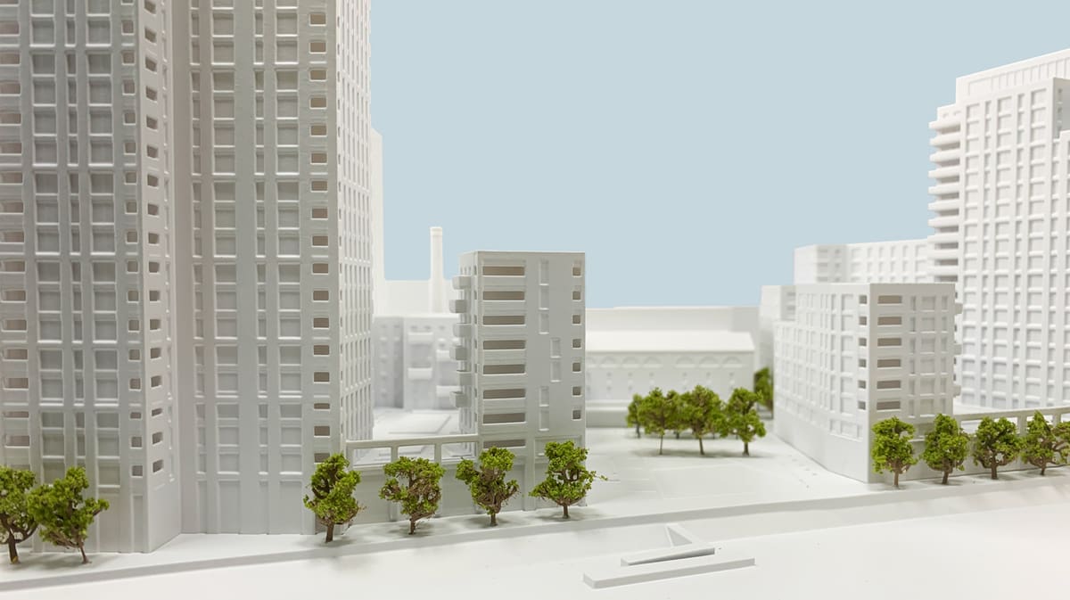
Lead image source: A model for Axis Mason by Fixie.
License: The text of "How to Prep Architecture Models for 3D Printing" by All3DP Pro is licensed under a Creative Commons Attribution 4.0 International License.