![Featured image of [Project] Automated Origami Swan](https://i.stageall3dp.com/workers/images/fit=scale-down,w=1200,h=675,quality=79,gravity=0.5x0.5,format=auto/wp-content/uploads/2019/04/27175750/origami-3d.jpg)
[Project] Automated Origami Swan

Take the ancient art form of origami into the future by turning a paper swan into a kinetic sculpture. Using a 3D printed case, an ItsyBitsy-powered servo motor, and fishing line, you can create an origami swan that flaps its wings.
Back in the sixth century, far before the time where we could watch physical objects materialize from the extruder of a 3D printer, people in Japan were creating interesting 3D objects by folding paper, which was a luxury item at that time, into origami art.
Now, with the help of 3D printing technology, we can bring origami into the age of automation. A student from Minnesota with an interest in engineering, who goes by the name of rpreston01 on the DIY-centric platform Instructables, recently shared an instructional project detailing how to make a moving origami kinetic sculpture.
This is a terrific project for those who want to learn about the ancient art form of origami, the basics of using servo motors with an Arduino micro-controller, as well as an introduction on how to solder electronics. By tying fishing wire to the wings of an origami swan, which will sit atop a 3D printed base, you can bring this majestic bird to life.
Let’s take a closer look at what you need and how to make this automated origami swan.
What You Need & How to Build it
The STL files for the 3D printed case, which is where the electronics will be housed, can be downloaded from Thingiverse. Comprised of two parts, the base can be 3D printed without support structures. A high layer resolution is recommended to ensure that the screws will properly fit into screw holes on the case.
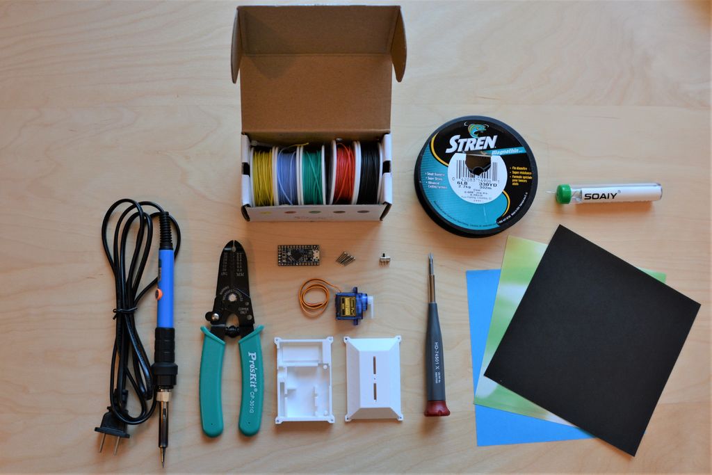
Aside from the 3D printed case, you’ll also need to hone your paper folding skills and acquire some non-printed components. A soldering iron is also required for the electronics assembly. Here’s what else you’ll need:
- Fishing line
- Wire
- Wire stripper
- Small screwdriver
- Small computer screws
- </li> <li>Origami paper
- Arduino
To program the Arduino, you’ll also need to download Arduino IDE software. Next, plug in the Itsy Bitsy to your computer and follow the directions laid out on the Adafruit website. Once you have the Itsy Bitsy set up, it’s time to start the assembly process.
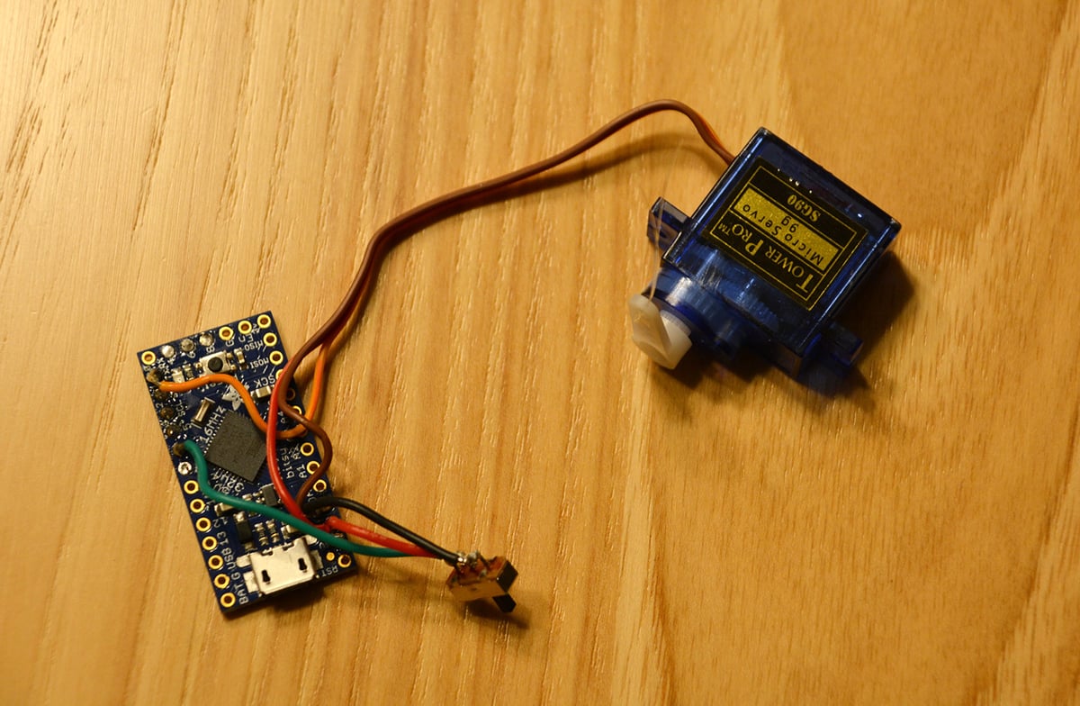
The creator of the project starts with wiring the electronics, which is fairly straightforward. Soldering should be done outside of the 3D printed case, but throughout the wiring process, you should periodically check to ensure that everything fits into place. Connect the red wire to the 5v pin, black and brown wires to the ground pin, and the colored wires from the servo and switch go to whichever numbered pin you prefer.
The programming and calibration process is also pretty simple. The goal is to have the Itsy Bitsy direct the motor to spin back and forth at 180 degrees when the switch is on. You can find the code and programming instructions in the programming and calibration section of the Instructables project page.
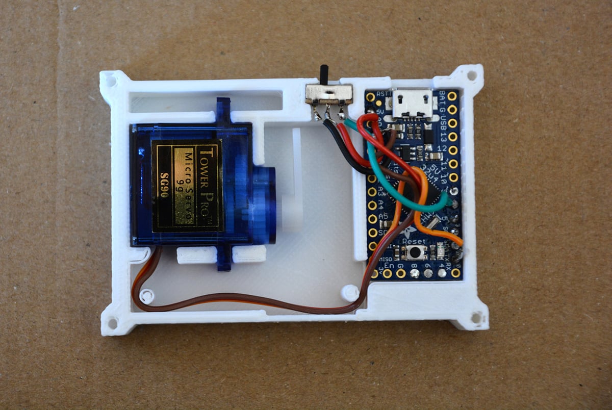
Now comes the fun part: origami time! The folding instructions are a bit intricate, but they’re laid out clearly in 12 steps by rpreston01 on the project page. Once you have your origami swan created, it’s time to put everything together. First, make sure that all of the electronics are in the right place (as pictured below).
Taking two strands of fishing line, tie them to the end of the servo arm, feeding the other end of the strands through the small hole placed in the middle top of the case. Next, place the top of the case on the base and tighten the computer screws in each corner. Make sure the fishing line is still fed through the hole before the screws are secured.
The origami swan will be placed in the slits on the top of the case. Finally, tie one of the two strands of fishing line to each of the swan’s wings, leave minimal slack when the wings are at their natural resting position. After everything is set up, cut away the excess of the fishing line.
License: The text of " Automated Origami Swan" by All3DP is licensed under a Creative Commons Attribution 4.0 International License.