AutoCAD 3D Drawing: All You Need to Get Started

Ever wondered what else you could do with AutoCAD aside 2D drafting? Read along to learn about AutoCAD's 3D drawing capabilities.
When it comes to 2D drawing, AutoCAD is a leading program in the design industry. However, hidden behind a little gear-shaped icon inconspicuously lurking on the lower corner of your AutoCAD screen is a completely different realm of opportunities… 3D!
In this article, we’ll discuss the main competencies of AutoCAD, zeroing in on 3D drawing and what it is. After that, we’ll take a look at the user interface and present an overview of relevant tools for 3D drawing. Lastly, we’ll walk you through two basic tutorials to design simple 3D shapes.
Let’s get started!
Usage
AutoCAD has grown into an indispensable tool for its target audience, and this can be traced to seamless design collaboration, tailored functionalities, and new features in subsequent releases, allowing you to work smarter instead of harder.
AutoCAD’s Popularity
Many a time, people attribute the term “CAD” to AutoCAD. One such reason is AutoCAD’s target market, which spans across but is not limited to the architecture, engineering, and construction (AEC) and product design and manufacturing (PDM) industries.
AutoCAD 2D is trusted by millions of users worldwide, especially for drafting, annotations, customization with add-ons and APIs, scripting, and so on. AutoCAD’s value proposition cannot be complete if automation, reliability, and its legacy CAD format (DWG) aren’t mentioned. Speaking of automating workflows, AutoCAD has specialized Plant 3D, mechanical, electrical, and plumbing (MEP), and architectural toolsets, among others.
It can sometimes be difficult to imagine the true size of a shape or to properly communicate the design idea, especially when it comes to complex geometries. One solution is to draw in 3D, and depending on the use case and workflow, AutoCAD can work along a powerful solution like Inventor, with both programs complementing each other.
That said, 3D drawing in AutoCAD can allow for a deep understanding of the 3D world, without needing to increase your software setup. Let’s glance through what this process looks like through a basic modeling workflow.
Basic Modeling Workflow
In order to create 3D models in AutoCAD, a standard simplified workflow would look something like this:
- Set up your drawing in the 3D workspace. To do this, you first select which work surface you want to begin designing on by orienting your X-, Y-, and Z-axes.
- Create your 3D drawing’s basic geometry using the special drawing commands found in the ribbon. (Don’t worry if you don’t know what this is, as we’ll discuss it below.)
- Once your 3D shape is created, you can carry on to the modeling phase using operations like Extrude, Add, Subtract, and so on.
Now that we have a general idea of what the workflow looks like, let’s define some terms so that we’re all on the same page before we move on to two possible methods.
Defining 3D Drawing
The idea of drawing in 3D can be difficult to understand at first. Indeed, the term “3D drawing” seems to differ in meaning depending on who’s using it and in what context. You might wonder what makes it different from 2D drawing, or you might think, “Is 3D drawing just a fancy way of saying 3D modeling?” Let’s answer those questions.
Sketching & Drawing
It’s common to hear the words “sketch” and “drawing” used interchangeably. With respect to CAD, one way to think of it is: There’s the action of creating a sketch, and there is the end product of what you just created, called a drawing (more like a noun and a verb).
Sketching is more aligned with artistic work; it gives the idea of a freehand illustration, which can be physical or digital. Sketching is expected to be quick, and would imply the first stage of a drawing process; it could also be understood as a loose drawing.
Drawing also involves creating images and shapes, but it features a more careful and accurate process with the goal of producing more detailed pieces. Relating this to AutoCAD, a drawing could mean the blueprint of a design that would be issued out for manufacturing or it could be a graphical representation of a design.
2D Drawing, 3D Drawing, & 3D Modeling
2D drawing, 3D drawing, and 3D modeling are interrelated. While “2D drawing” could mean engineering drawings, schematics, or blueprints, among others, it could also mean the action of creating them.
We can safely say that a 2D drawing, with an extra axis (Z) to tell the depth (height) of a geometry or object, is a “3D drawing”. Clients or individuals without a technical background tend to understand the drawing or design more when it’s in 3D. And the term “3D drawing” could also mean the action of creating 3D designs.
On the other hand, “3D modeling” would imply the action of creating graphical representations of objects by manipulating vertices in a virtual space. This would be characterized by Boolean operations, sketch manipulation, and more.
Now that we have a clearer understanding of what we’re referring to when we talk about sketching, 2D and 3D drawing, and 3D modeling, let’s get our bearings in AutoCAD.
UI & Layout
Before looking into how to create 3D drawings in AutoCAD, it’s good to have a general idea of where different tools and features can be found. Maybe you already know your way around a similar program, or maybe the following information can help you get started.
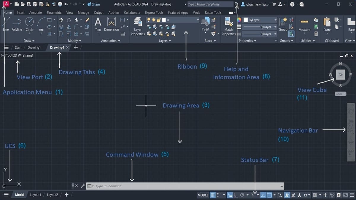
- Application Menu (1): The distinctive ‘A’, this provides a vertical list of tools to help you manage your AutoCAD files. You can import, export, save new copies, or print them, to mention a few.
- Viewport (2): Here you can find options to control 3D and 2D views and visual styles (like wireframe and conceptual view), especially during the drawing process.
- Drawing Area (3): As the name implies, everything you can draw appears in this area. As you move your mouse within this area, a drawing cursor (crosshair) appears, allowing you to point to locations within the drawing area.
- Drawing Tabs (4): Here you can create new drawings by clicking on the ‘+’ tab or switch between open drawings. Think of this as having multiple drawing papers stacked together, with individual tabs giving you the ability to switch between them with ease.
- Command Window (5): Commonly called the “command prompt” or “command line”, this displays the feedback on the AutoCAD commands as you use them.
- UCS (6): The User Coordinate System (UCS) gives the information on how your drawing is oriented in the 2D or 3D space.
- Status Bar (7): Users can get information at a glance about the state of the drawing here, and it holds a set of tools that assist in the drafting and modeling processes.
- Help and Information Area (8): This section provides the support, links, and possible answers relating to the use of the software.
- Ribbon (9): This houses a set of panels that group tools and features together, and it can also be called a toolbar in other CAD software. Simply put, while the ribbon contains a panel, the panels are segmented using names that are displayed in the title bar at the bottom (e.g. “Draw”, “Modify”, “Annotation”, etc.).
- Navigation Bar (10): This contains commands used to zoom, pan, and orbit your design. You will also find advanced tools for viewing 3D models here.
- ViewCube (11): Common to almost all CAD programs, the ViewCube is the go-to tool during 3D modeling to manipulate the viewpoint.
AutoCAD 3D Drawing
3D drawing in AutoCAD refers to the creation of 3D models using the 3D, 2D, and even 1D features and commands found within the drawing environment. Some examples include the PolySolid, Rectangle, and Line features respectively. Depending on the use case, the resulting model can be further utilized to create orthographic, isometric views, and auxiliary views, among others.
We’ll look into how to create 3D drawings by following two different paths: the first by illustration and the second by 3D modeling.
Drawing by Illustration
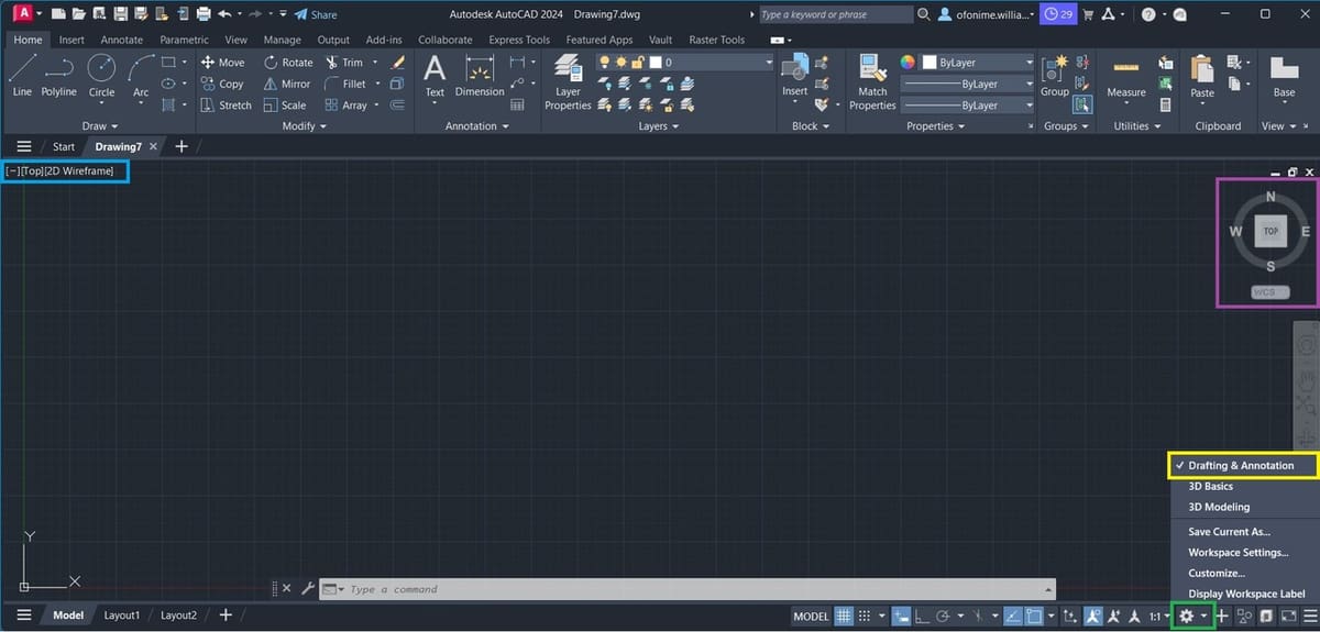
Once you’ve successfully installed and opened up your AutoCAD, you’ll be on the AutoCAD Drafting and Annotation UI by default, with all the toolsets required for professional tasks.
In case you were working on a previous project or you’re not sure, you can confirm that “Drafting and Annotation” is active (see yellow above) via the little gear icon on the extreme right corner of your status bar (see green). Also locate the Viewport, then left-click to select “2D Wireframe” and “Top” one after the other (see light blue), to ensure that your ViewCube is as shown above (see purple).
Basic Workflow
For this tutorial, we’ll make use of a set of tools from the Draw panel to create our base shape. Next, we’ll join the base shape to a circle placed above it, using vertical lines. We’ll modify this geometry, followed by the preparation of our drawing using tools from the Annotation tab.
Let’s construct a representation of a 3D shape using AutoCAD 2D drawing commands.
3D Drawing with Drafting Tools
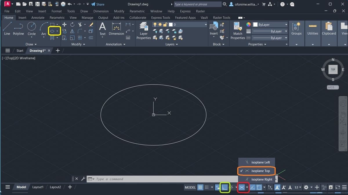
- Once you’ve gotten your bearings, hover on the Status Bar to locate the Isodraft feature, and left-click to activate the isometric drafting mode (see red above).
- Press ‘F5’ or “Ctrl + E” to switch between isoplanes to “isoplane Top”, or select it from the options (see orange).
- Press ‘F8’ or left-click to select the Orthomode from the Status Bar (see green). This restricts your line to be drawn in an orthogonal manner, resulting in straight lines that can only be drawn within a set incremental range of angles from the reference point.
- From the Draw panel, locate and select the ellipse and then the “Axis, End” tool from the drop-down menu (see yellow). Left-click on the “Isocircle” option displayed on your Command Window. The “Isocircle” option would only be available when Step 1 has been carried out.
- Move your cursor from the command line to the center of your drawing area. As you move, you’ll notice a prompt close to the crosshair, “Specify center of isocircle” alongside an input box. This is your “Pointer Input”. Proceed by typing ‘0’, press the “Tab” key, input another ‘0’, and press “Enter”.
- Type “15” in the input box to specify the radius of the isometric circle (this particular input box is called the “Dimension Input” ), press “Enter”, then “Esc”. This creates an isometric circle with a diameter of 30, positioned at the center of the drawing area (where X-, Y-, and, Z-axes intersect and are of 0 magnitude).
We’ve just created our base sketch. If the created isometric circle seems missing or is partially seen in your drawing area, simply type ‘Z’, press “Enter”, type ‘A’, then press “Enter” again. This brings the base sketch to the center of your drawing area, then you can zoom out a bit via your middle mouse button to obtain the above image.
Next, we’ll replicate a three-dimensional solid with a curvilinear geometric shape, known as a cylinder. So let’s initiate a few settings from our Status Bar for a better drawing experience.
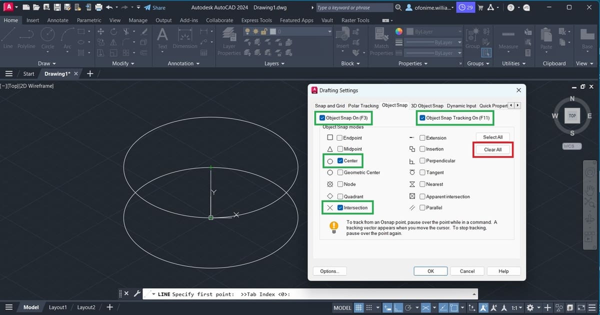
- Within the drawing area, type “OSNAP” and press “Enter”; the object snap settings menu will pop up (you can type this command directly on the Command Window too). Left-click on the “Clear All” button (see red above), and only tick the settings as shown above (see light green).
- Press ‘F5’ to switch to “isoplane Right”. You can keep pressing ‘F5’ until you see “isoplane Right” in your command window, in case you missed it.
- Select a “Line” tool from the Draw panel, move to the center of the isometric circle and left-click when the “Center” snap symbol appears (a tiny green circle, which helps you position the tip of your line).
- Move your cursor upward to draw a vertical line, type “10” in the “Dimension Input” box that appears to specify the height of the line, then press “Esc” to end the command.
- Repeat Step 7, but this time just tick “Endpoint”. Press ‘F5’ to switch to “isoplane Top” and repeat Step 10 above.
- Move to the Drawing Area and select the top (tip) of the vertical line, drag your drawing cursor towards the right, and type “15” in the “Dimension Input” box to specify the diameter. Now we’ve drawn another isometric circle above the base sketch.
- Switch to “isoplane Right” (‘F5’), then repeat Step 7, but this time allow just the “Quadrant” to be ticked. We need two vertical lines to join the top and bottom isometric circles.
- Select a “Line” tool from the Draw panel, move towards the circumference of the bottom isometric circle, and left-click when the “Quadrant” snap symbol appears (a tiny green polygon symbol that helps you position the tip of your line on the quadrant of the isometric circle).
- Move your drawing cursor vertically towards the top isometric circle and left-click when the “Quadrant” snap symbol appears again, press “Esc” to end the command.
- Sometimes, the line can be overextended. If so, type “Trim” directly on your command line and press “Enter”, then move to the overextended part of the line to trim it off (you’ll notice the red marker showing the line that would be trimmed off).
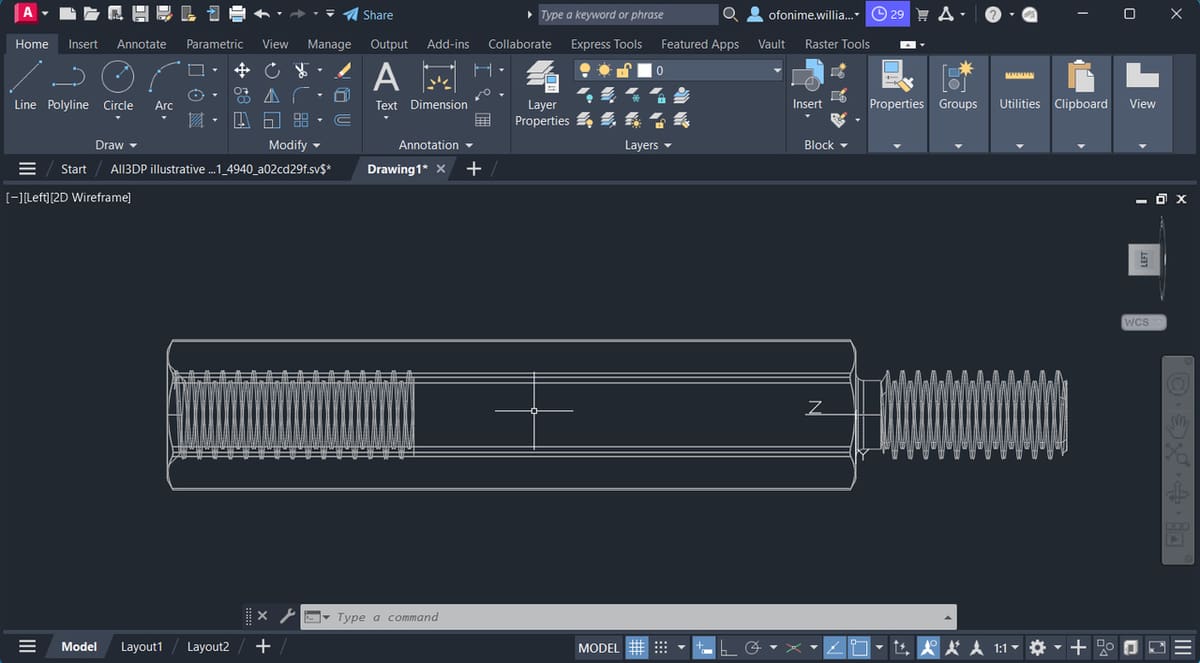
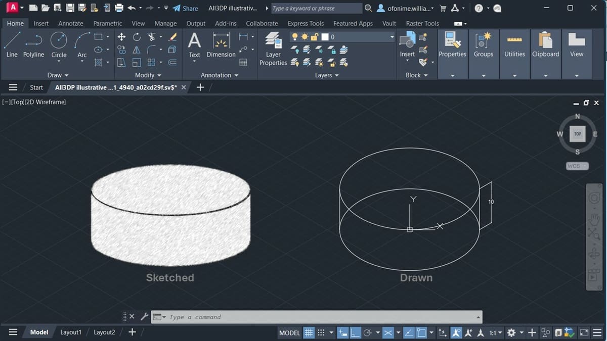
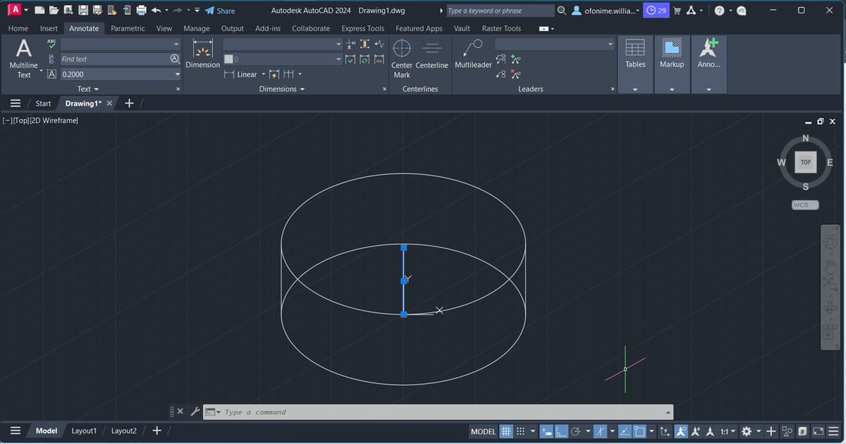
We’ve constructed an illustrated 3D drawing of a cylinder with a height of 10 and a diameter of 30. Notice the highlighted vertical line in the center of the circle – we no longer have a need for this line, so you can select it and press “Delete” to obtain a clear representation of the cylinder.
Adding Details
We’ll add details to our drawing and print it out – note the three tabs in the bottom left corner of your drawing area (“Model”, “Layout1”, and “Layout2”).
- Press ‘F5’ to return to “isoplane Top” and left-click to select the tab “Layout1” from the status bar (see green above).
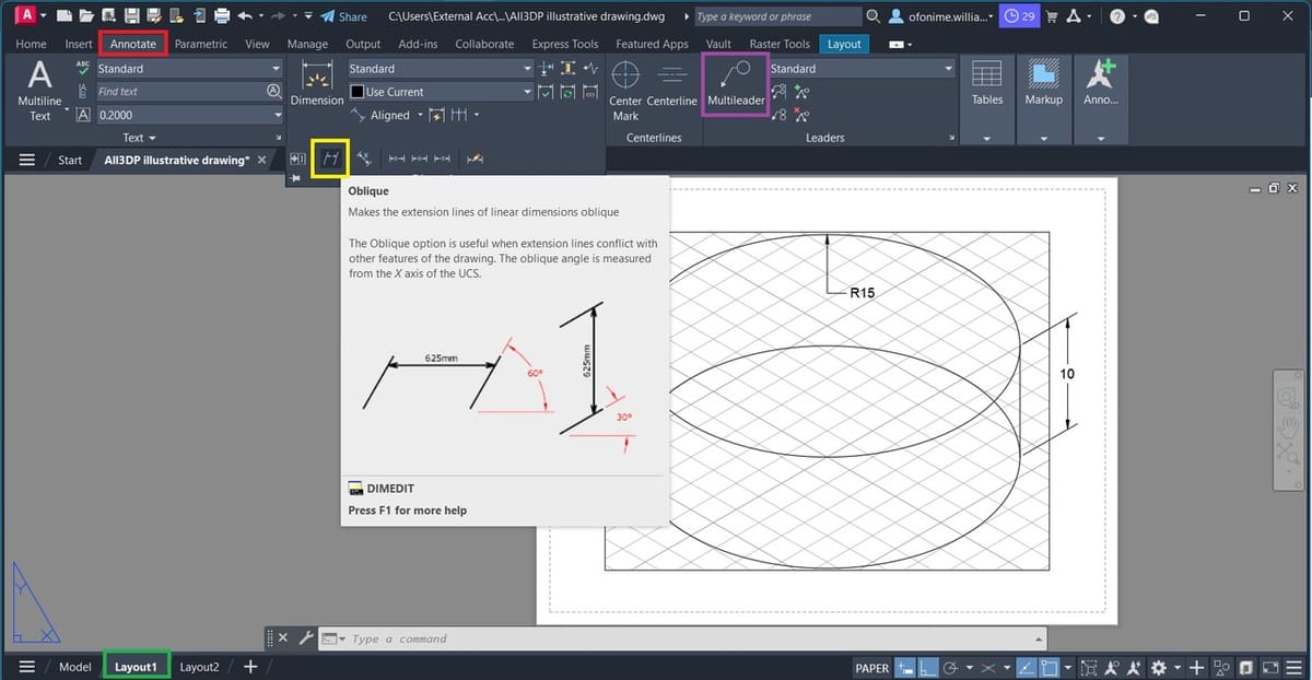
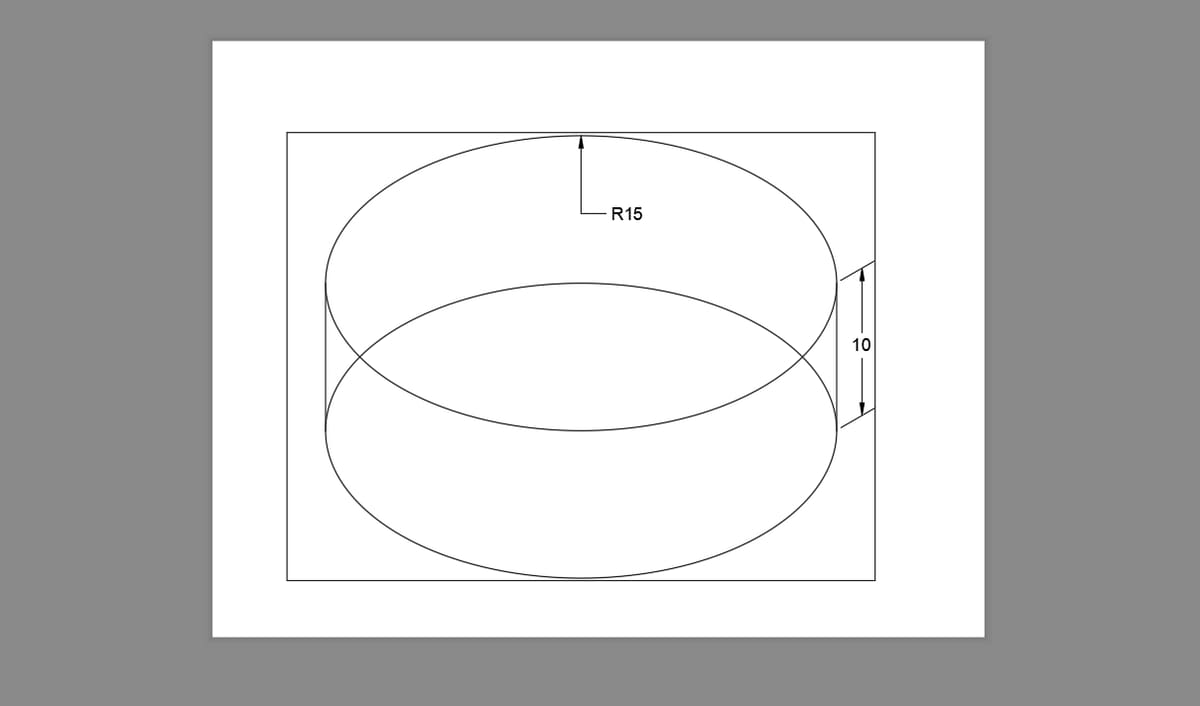
- From the ribbon, switch to the Annotate tab (see red). Type “DIMALINGED” within the Drawing Area or directly on the Command Window, then select the top and bottom quadrants on your cylinder to dimension its height as shown above.
- Locate and select the “Multileader” from the ribbon (see purple) and click on the circumference of the cylinder’s top. Move your cursor down a bit and type ‘R15’ in the annotation box that appears, then click any area on the drawing layout. This adds the radius of the cylinder, as shown above.
- Type “DIMEDIT” and select “Oblique” from the Command Window (see yellow), then press “Enter”. Select the dimension of the cylinders’ height (10), press “Enter”, then input “30” in the “Dimension Input” box that appears. This specifies the oblique angle and properly positions your dimension.
Notice how the dimension aligns with the isometrically drawn cylinder, as shown above. Next, we’ll prepare and output the detailed drawing.
Output
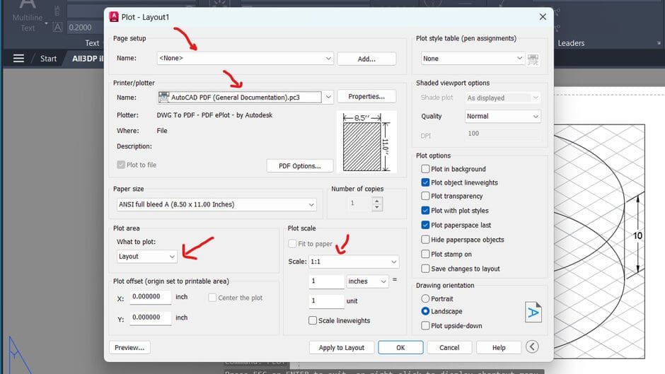
- Move to the Drawing Area or the Command Window and type “PLOT”, press “Enter”, then select “Continue to plot a single sheet” to obtain the image shown above. Ensure your selected options are as indicated in red. Notice how the plot area shows “Layout”; this represents your active layout, in this case “Layout1”, simply think of this as your drawing paper.
- Once you’re satisfied with your setup, simply select the “OK” button to obtain the drawing above.
Drawing by 3D Modeling
Modeling with AutoCAD 3D is centered around creating and manipulating a mesh, surface, or solid shape. AutoCAD’s 3D interface contains primitive shapes, 3D features, setup tools, and commands for creating, modifying, viewing, and printing 3D objects. Most times, we’re constrained to combine tools from AutoCAD 2D and AutoCAD 3D to obtain the desired drawing; this is one reason why the 2D Draw and Modify panels are within the 3D workspace.
Basic Workflow
In the context of 3D modeling, when we lay emphasis on the physical fidelity of objects, solid modeling comes into play. In solid modeling, we represent a 3D shape by defining the limits of its volume; this method is called BREP (B-rep). B-rep is short for “boundary representation”, whereby boundaries (or connected surface elements) are used to define the model.
Note that the term B-rep applies to both surface and solid models, and for this tutorial, our 3D shape will be a cylinder, represented as a solid model (B-rep) in AutoCAD.
After switching to the 3D modeling environment and getting our bearings in the modeling environment via the Home icon, we’ll leverage a primitive tool from the modeling tab to create our geometry (solid B-rep).
In a nutshell, we’re creating a 3D shape using AutoCAD’s 3D drawing command. The final model is used to create the desired 2D drawing, where applicable. Let’s dive right in!
3D Drawing Using B-rep
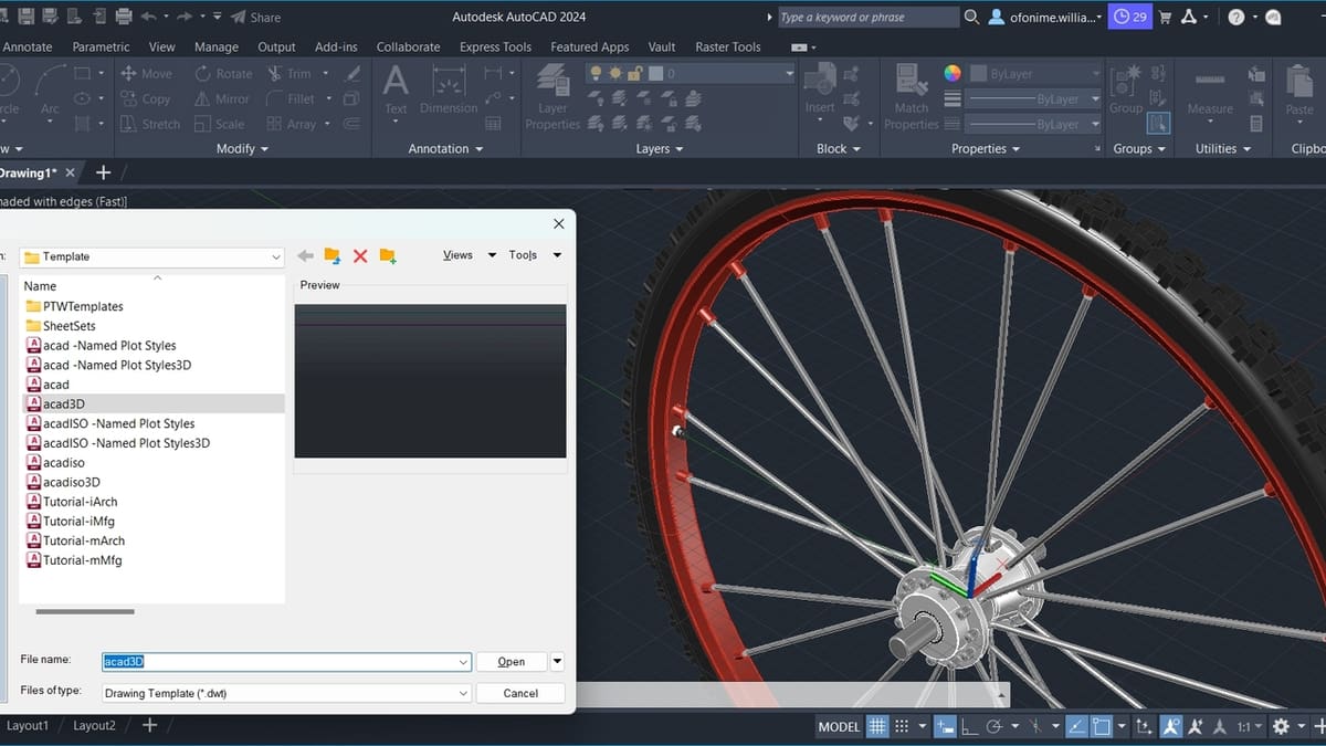
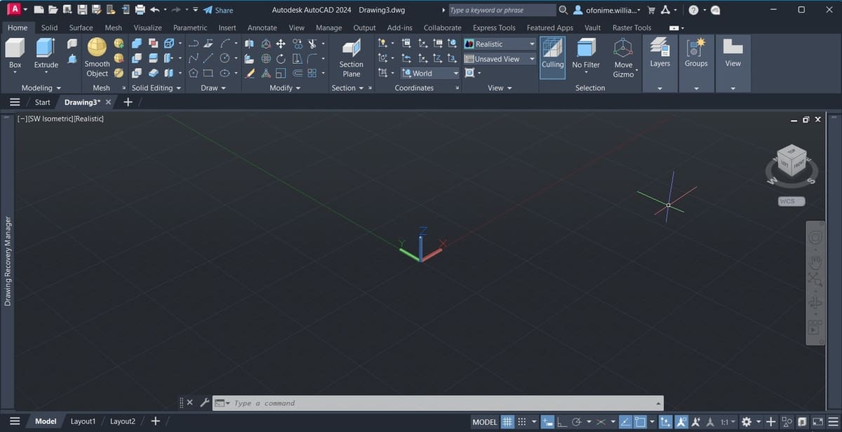
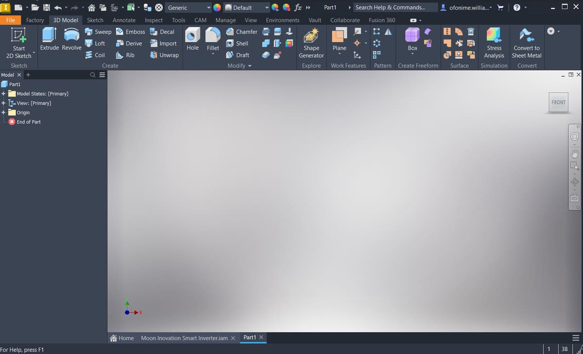
- Open AutoCAD, press “Ctrl + N”, and select the template “acad3D” to launch the 3D environment. If you were already in the 2D Drafting and Annotation environment, then select the gear icon on the status bar (see yellow above), and switch to the 3D environment.
- Move your cursor very close to the ViewCube and the “Home icon” should appear (a tiny house-like icon close to the ViewCube). Left-click this “Home icon” to initialize your workspace as shown above.
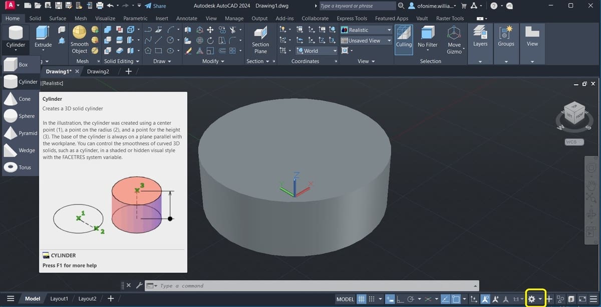
- At the extreme left corner of the ribbon, locate the Modeling panel, and left-click the drop-down as seen in the image to select the “Cylinder” tool (a primitive tool).
- Move to the drawing area so the “Pointer Input” box appears, type ‘0’, press the “Tab” key, type ‘0’ again, then press “Enter”. This positions the cylinder to be drawn at the center of the environment.
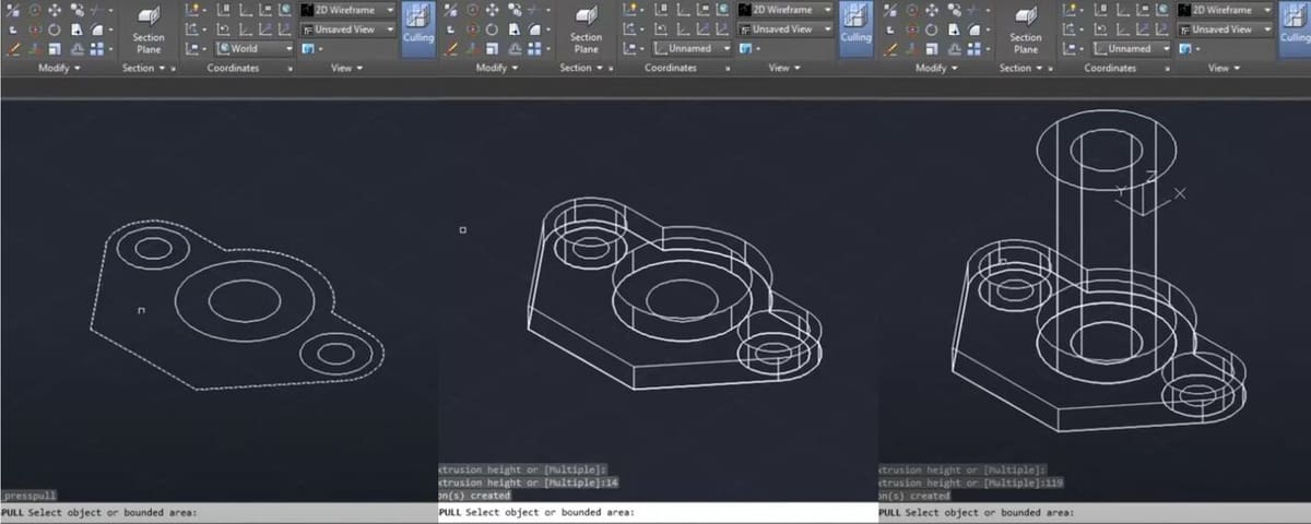
- Move your cursor outward a bit, type “30” in the “Dimension input” box that appears to specify the base diameter of the cylinder, press “Enter”, then type “10” in the “Dimension input” box that appears to specify the height of the cylinder.
We’ve created a cylinder (solid B-rep) with a diameter of 30 and a height of 10, positioned at the center of the 3D modeling environment.
- Just like in the previous tutorial, simply left-click to select the tab “Layout 1” from the extreme left of the Status Bar (see yellow above).
- Left-click to highlight the boundary lines of the drawing page as shown (red arrow), then press “Delete” to obtain a clear drawing sheet.
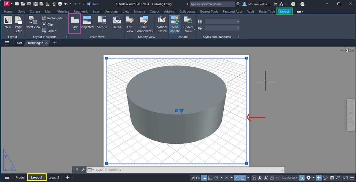
- From the ribbon, switch to the Layout tab (see green).
- On the Layout tab, in the Create View panel locate the “Base” feature (see purple), click on it and select “From Model Space”. Move into the drawing sheet (bottom right of the sheet), and left-click to place the first view of the cylinder.
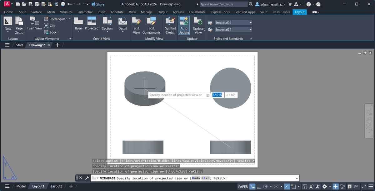
- Select “Exit” from the prompt displayed on the dialogue box, move your mouse to the left where there is an empty space, then left-click to place the second view.
- Move your mouse to the top where there is an empty space, left-click to place the third view, then move diagonally as shown in the image to place the isometric view, and press “Enter” (this creates a 2D drawing view from your 3D model).
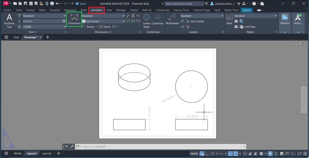
- Just like in the previous tutorial, from the ribbon, switch to the “Annotate” tab as shown (see red above).
- We’ll use the “Dimension” tool to add the radius and height of our cylinder. Left-click on the “Dimension” tool (see green) then move to the drawing views you just created. Left-click the edge of the cylinder and move your cursor outward to dimension the cylinders’ height.
- Similar to the previous tutorial (under “Output”), move to the drawing area or click on your command window and type “PLOT”, press “Enter”, then select “Continue to plot a single sheet”. A “Plot” window appears; ensure that your selected options are as indicated in red in the previous tutorial.
Resources

For further help using AutoCAD, you can visit Autodesk’s support page or the AutoCAD Forums. There are also heaps of tutorials online, from both official and third-party sources. And for even more help from the community, you can check the subreddit and post any questions or doubts.
If you’re new to AutoCAD, check out our beginner design tutorial to help you get started. If you’ve used 3D drawing to create a model and want to see it in real life, check out our guide to 3D printing from AutoCAD.
Last but not least, if you’ve created a 3D drawing and want to see it brought to life but you don’t have a 3D printer handy, try the professionals at Craftcloud.
Alternatives
Sometimes, AutoCAD’s features won’t necessarily meet your needs. In moments like this, alternative tools can be very handy. The following alternatives are selected based on how closely related they are to the subject of discussion, namely the user interface, user experience, functionalities, and ease of interoperability.
DraftSight
DraftSight is professional 2D CAD software that can be used to create, edit, view, and mark up any kind of 2D drawing or DWG file, and it has a similar UI to AutoCAD. Both products share a similar target market and offer features and tools like drawing, annotation, parametric constraint, and dynamic blocks, to mention a few.
DraftSight does contain some unique features like “Topo Tracer”, for converting topographic images into DWG format, and a G-code generator. However, because Autodesk created the “.dwg” file format for AutoCAD, this latter program is arguably the most efficient and accurate tool to edit and view such files. And while AutoCAD has about seven specialized industry tool sets across different fields, making automation effective, DraftSight is a great choice when it comes to affordability, as a year’s professional license costs roughly what a monthly one of AutoCAD’s does.
Inventor Professional
While Inventor has a dedicated sketch and annotation tab like AutoCAD and the parameters constraints and modification features produce similar results, its 3D design offers a unique level of control over the designs.
Users can easily select and integrate standard components, change parameters, and generate 3D models and related drawings easily. If a machine can be designed in AutoCAD, Inventor will go beyond to simulate how the machine works and reacts to external force. Modeling in Inventor is parametrically driven, meanwhile it’s geometrically driven in AutoCAD. Inventor has a unique way of distinguishing between assembly and part files, while AutoCAD operates an all-in-one file.
However, Inventor at its core is mechanical design software and falls short of AutoCAD’s multi-industry use case. AutoCAD integrates with industry-specific tools such as AutoCAD Architecture, Mechanical, and Electrical, to mention a few. As powerful as Inventor is, it’s limited when compared to AutoCAD’s 2D drafting capability, translating large plans to 3D, and making and interpreting DWG edits.
Fusion
One outstanding feature in Fusion (previously Fusion 360) is its Timeline, which allows you to go back in time and do things differently on your design, and this updates upstream. Product-based, this comparison would be unfair, since Fusion is a cutting-edge product design and development tool (imagine integrating CAD, CAM, CAE, and PCB in a cloud-native platform). Fusion has just the right amount of tools for creating parametric sketches in a very simplified manner. One can create automated and easy-to-edit 2D drawings, and Fusion features toolsets like create, modify, and constraints, just like AutoCAD.
Meanwhile, AutoCAD 3D can be very productive if you intend to easily manipulate or generate freehand 3D shapes, without the fear of errors due to broken relationships (you will need to be in “Direct edit” mode in Fusion to achieve this). AutoCAD will let you perform operations like reusing and storing design data, in a smart and superfast way. However, this is not so in Fusion, both in the approach and speed of implementation.
It’s professional practice to limit the number of sketches and constraints on a Fusion design, as it could make your design unstable and take longer to compute. Meanwhile, AutoCAD can carry as many 2D and 3D drawings as required, separated by layers and drawing tabs (especially if you know how to optimize your design workflow).
SolidWorks
SolidWorks is adopted in the design and manufacturing industry for designing intended in the most realistic, innovative, and professional way, similar to Inventor.
Apart from AutoCAD lording over SolidWorks in the areas of 2D drafting and annotation, AutoCAD 3D can also be a great choice over SolidWorks with respect to the nature of the project.
Imagine drafting and translating a building plan or blueprint to 3D; this would obviously be easily implemented in AutoCAD with less worry over errors due to broken relationships. You would likely run into trouble doing this with SolidWorks, as the freedom and toolset for speedy implementation of such a project might not be readily available.
License: The text of "AutoCAD 3D Drawing: All You Need to Get Started" by All3DP is licensed under a Creative Commons Attribution 4.0 International License.