Blender: Displacement Maps – Simply Explained

Tired of having your textures look plain and ugly? Read all about Blender's displacement maps and learn how to add realism to your models.
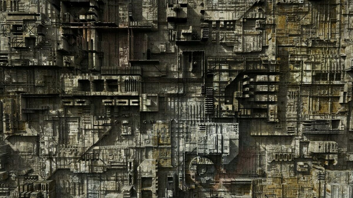
Displacement maps, similar to bump maps, are a common way to enhance the look and texture of rendered 3D models without having to create super detailed and complex geometries.
Unlike bump maps, which only change the surface normals, displacement maps fake the position of vertices within a model so that it looks like it has some roughness to it, creating a “3D” effect even before rendering – but in reality, the 3D model’s surface remains unchanged. This provides a series of benefits that we’ll take a closer look at, and we’ll also dive into how to use them together with Blender’s Cycles renderer.
It’s important to note that, although most renderers allow the use of displacement maps, a few exceptions including Blender’s own Eevee still don’t officially support them. There are some workarounds to replicate the effect of displacement maps in Eevee, but in this tutorial, we’ll be sticking with Cycles. If you prefer Eevee, though, fear not! Blender is planning to release their new “Eevee Next” renderer in March 2024, which promises to officially support displacement maps.
But let’s get back to this tutorial. Before we go over how to create or import displacement maps, we’ll look into how they work and what the benefits are. To wrap things up, we’ll share a few tips and tricks. Let’s dive in!
How Do They Work?
We’ve briefly mentioned what displacement maps are and what they do, but how do they work?
To help answer this question, it’s important to understand how they’re made.
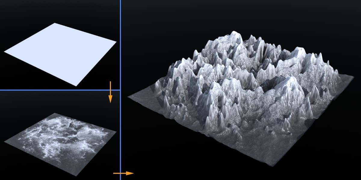
One of the most common ways to create a displacement map is by modeling a highly detailed texture-like geometry and then exporting its height data into an image file (displacement map). The displacement map is then imported into any new geometry via a series of nodes (depending on the software used), which upon rendering “mimics” the look of the previously modeled geometry. This allows us to “fake” the effect of, let’s say, a tiled rooftop or rocky terrain on an otherwise perfectly flat geometry.
However, it’s important for the new geometry to be properly subdivided as it achieves this effect by faking the new position of those vertices. This means that, if it’s not properly subdivided, the effect won’t be as noticeable or won’t appear at all, so preparing your new geometry is important, to say the least.
Different Types
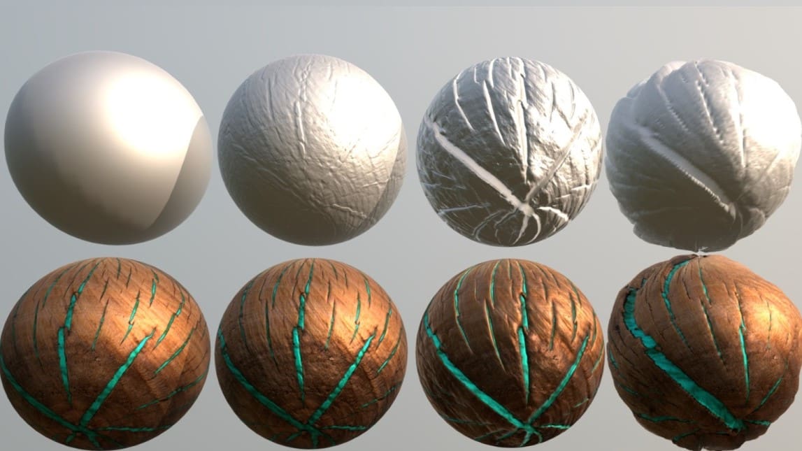
Displacement maps are used in combination with materials to achieve a more realistic look. Sometimes good lighting is necessary to better appreciate the effect of displacement mapping.
It’s worth noting that there are two different types of displacement maps:
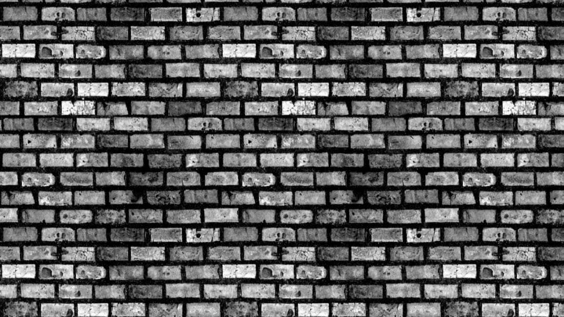
- Height maps: Also known as grayscale maps, they show elevation as shades of gray, with brighter and darker areas representing higher and lower elevations, respectively.
- Vector displacement maps: These are more complex than height maps and don’t just store height data but movement too. They use RGB channels to represent data rather than grayscale.
Different Displacement Types
Not to be confused with the previously mentioned displacement map types, Blender offers three different types of displacement methods that vary slightly from each other depending on the user’s needs.
These methods are used in combination with the displacement maps to achieve different results. The methods are as follows:
- Bump only: Most memory efficient, only affects the shading.
- Displacement only: Most accurate but memory intensive.
- Displacement and Bump: Best of both worlds.
Bump-only maps are used for small details such as wrinkles or skin pores, whereas displacement-only maps are used for higher quality textures that provide a real 3D “height” effect no matter which angle you look from.
What Are the Benefits?
At first, it may seem like using displacement maps just adds extra work and complexity to your materials for an effect that could be achieved with some fine modeling. But we assure you, displacement maps can be a game changer, especially for more complex scenes. Some of the benefits include (but aren’t limited to):
- Reduced polygon count: Displacement maps can allow you to reduce the total polygon count from your models.
- Reduced memory usage: Directly related to the previous benefit, a lower poly count will reduce the total memory and CPU usage required to work with your scene.
- Ease of use: Different displacement maps can be swapped out and tested in a matter of seconds, allowing for various effects to be tried out without having to model everything separately.
- Easier modeling: With the ever-increasing gallery of free displacement maps such as those you can find in Poly Haven, adding them to your project can take away time and work that would have instead been spent trying to model everything from scratch.
Due to the nature of displacement maps, you can always preview the “3D effect” from the viewport itself without having to render it every time.
In the following section, we’ll guide you through the steps to create a displacement map node setup in Blender.
Creating a Simple Displacement Map
Creating a displacement map node setup in Blender is actually easier than you might think! First, we’ll guide you through the steps required to create your own displacement map from Blender itself, and later we’ll expand this setup to use external maps.
- Split the workspace to show the 3D viewport and shader editor; the easiest way to do this is by clicking the “Shading” tab on the top menu.
- Delete the default cube and create a UV sphere by pressing “Shift + A”, then selecting it from the “Mesh” drop-down menu.
- Assign a new material to the sphere by clicking on the “New” option next to the materials symbol at the top of the shading editor. You can also add it in the Material Properties Editor by clicking on “New”.
- Add a “Displacement” and “Noise texture” node by pressing “Shift + A” while inside the shader editor, then typing the name of the node in the search bar and finally placing them anywhere you like.
- Connect the Displacement node to the “Displacement” input of the “Material Output” node.
- Connect the “Fac” output of the Noise Texture node to the “Height” input of the Displacement Node.
- Confirm that you’re in Cycles (or change to it if your renderer is set to Eevee). To do this, go to the “Rendering” workspace (tab at the top), select Cycles from the “Render Engine” drop-down menu to the right, and then return to the “Shading” workspace.
- Open the Material Properties Editor (in the Properties Editor to the right of the UI), and under “Settings” change “Bump only” to “Displacement and Bump”. Note that if you can’t see this option, it’s probably because the render is set to Eevee.
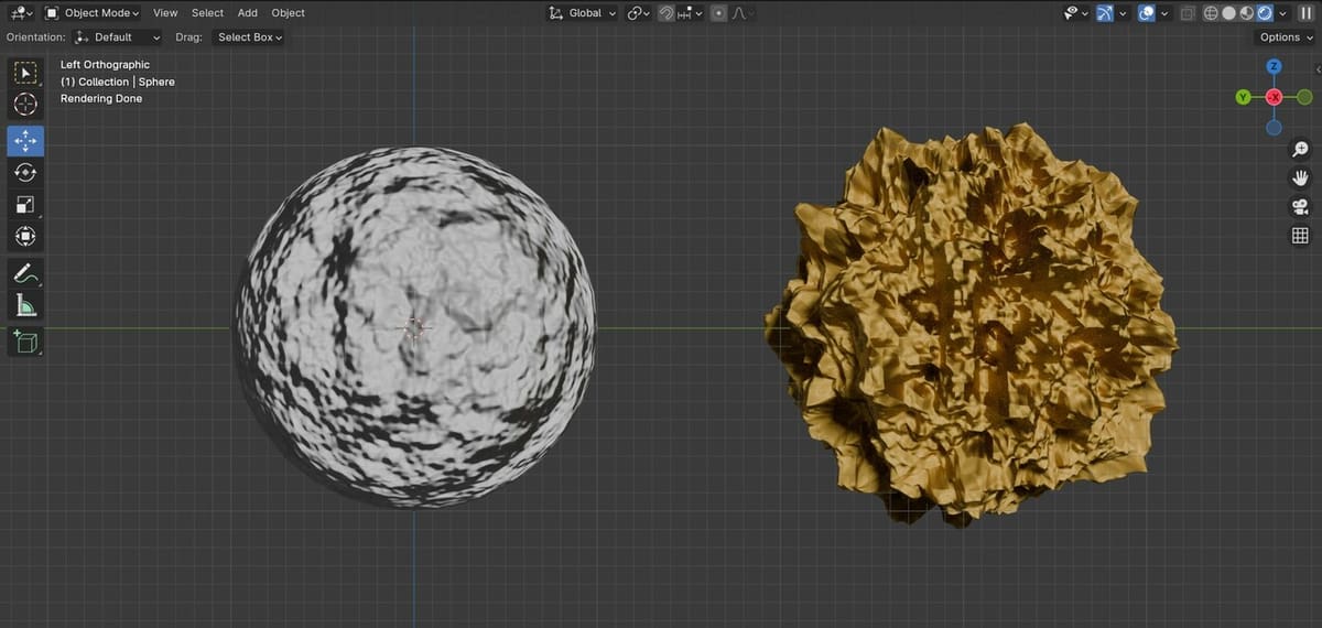
You can now check the results by switching to the Render view and seeing how the sphere looks like a small rocky planet. In order to see the displacement map effects in action, you don’t have to render the scene but you will have to be in the render view (from the top menus, “Render > Render Image” or hit “F12”).
Next up we’ll swap the noise texture for a real displacement map.
Importing Displacement Maps
We’ve learned how to create a displacement map setup in combination with an object’s material in Blender, so now we’ll do the same with a displacement map from a repository site.
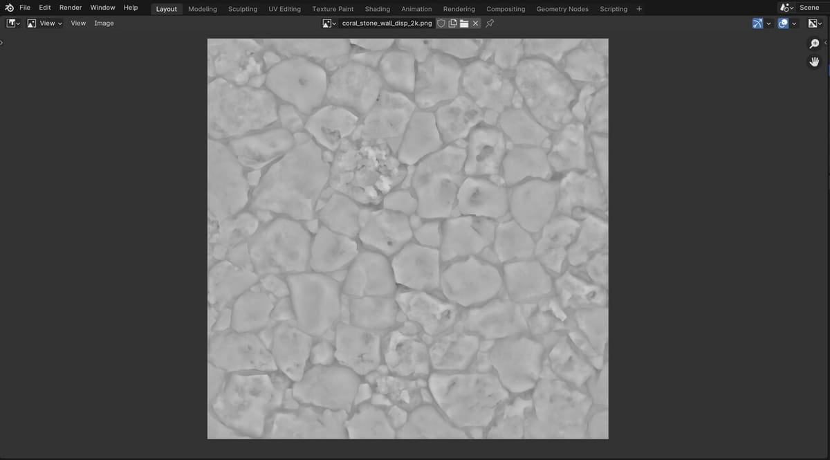
You can take a look at the materials available from the previously mentioned Poly Haven or from 3Dtextures, as they offer a large variety of material types, including displacement maps, some of which have a CC0 license. This means that you’re free to use them for any purpose but you can’t claim them as your own!
Once you’ve downloaded a material setup you are happy with, save it in a folder and follow the next steps to import it into Blender. Most materials from the sites we linked above include a displacement map file. Some of them may instead have a “bump map” file, but don’t worry as they can also be used for this.
Enabling Node Wrangler
Although not essential, this built-in add-on makes the job of importing and setting up the material nodes much easier.
- From the top menu options, go to “Edit > Preferences”.
- Go to the add-ons tab and search for “Node Wrangler”.
- Enable the add-on and close the Preferences window.
Importing the Material Files
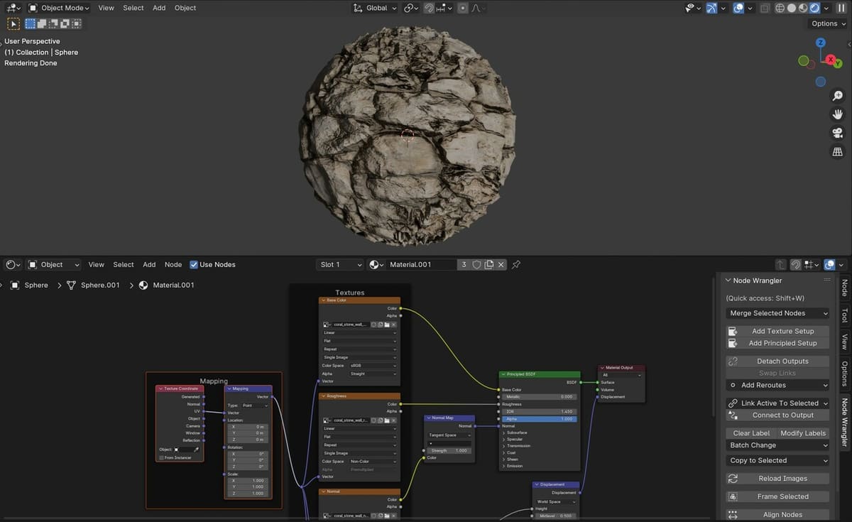
With the add-on enabled, we can now proceed to import the material we just downloaded. To do that, we will…
- Ensure the sphere and “Principled BSDF” node inside the Shader editor are selected by clicking on them.
- Delete the previously created displacement and noise texture nodes if you haven’t done so already. To do this, simply select them and press the “Delete” key.
- Open the toolbar by pressing ‘N’ on your keyboard, then locate the “Node Wrangler” tab and click on “Add Principled Setup”. Alternatively, you can press “Ctrl + Shift + T”.
- Navigate to the folder you saved the material in and select all the files, including the displacement map.
Blender has now imported all the files and connected the nodes to their respective inputs and outputs, saving us a lot of work.
Just like before, you can check the results by switching to the Render view and seeing how the new material looks on the sphere.
Tips & Tricks
We’ve now reached the end of our article on displacement maps; we hope you’ve found it useful! Before finishing, we’ll point out a few tips and tricks that may make your life easier when working with displacement maps, and Blender as a whole.
- Tweak the displacement scale: The Displacement node allows you to tweak the scale of the effect. In it, you can find a drop-down menu; it can be useful to set this node to “World Space” instead of “Object Space” so that it won’t matter if you subdivide your model too much: the displacement effect will match that of the displayed material.
- Don’t mix displacement maps from different materials: Although it’s possible to mix different materials, make sure to use the displacement map provided with each material setup or else they won’t look right (although this is a good way of achieving some rather silly results).
- Make sure you have a good lighting setup: This doesn’t just apply to displacement maps, but given their nature, your renders will look much better if paired with proper ambient or three-point lighting. We’ve found that using a Sun light really enhances the displacement effect when directed correctly. From the top menu options, go to “Add > Light > Sun”, click on “Shift + A” and from the drop-down menu go to “Light > Sun”. Or, if there’s already a “Light” object you’d like to change, select it from within the Scene Collection (top right of the UI), and in the Properties Editor, replace it with “Sun” (instead of “Point”).
License: The text of "Blender: Displacement Maps – Simply Explained" by All3DP is licensed under a Creative Commons Attribution 4.0 International License.