CAM Software – What Is It & What Does It Do?

Once upon a time, extensive knowledge and manual dexterity were required to machine parts. Find out the basics of CAM software, the tools that make CNC machining easy.
Before John T. Parsons introduced computer numerical control (CNC) machining in the 1950s, machinists had to undergo plenty of training and practice before they could skillfully operate machines. In fact, being a machinist back then was a badge of honor, as a single human was tasked with interpreting blueprints, identifying the required tools, defining speeds, and manually building parts.
Things changed after the introduction of CNC machines and CAM software. The latter has given manufacturers more control than ever to design and produce intricate details. If anything, the introduction of CAM software has entirely revolutionized manufacturing.
Computer aided manufacturing (CAM) software is a tool/program that uses numerical control (NC) to create detailed instructions (G-code) that drive CNC machines. CAM software streamlines the machining process and automates actions like drilling and cutting, which makes it ideal for high-quality manufacturing.
What Does It Do?
CAM software prepares a drawing for production, which is considered the last step in the design process. For that reason, you can think of CAM software as “slicer software” that translates drawings and data into detailed instructions to drive an automated tool.
CAM software uses G-code to communicate directly with the control machine. As a programming language generated from a drawing, this G-code “instructs” the tool on what to do. For example, it will tell the motors where to move, how fast to move, and the programmed path they should follow.
Behind the scenes, CAM software does a few things:
- Error checking: CAM software checks whether the model has any geometrical errors that can affect the manufacturing process.
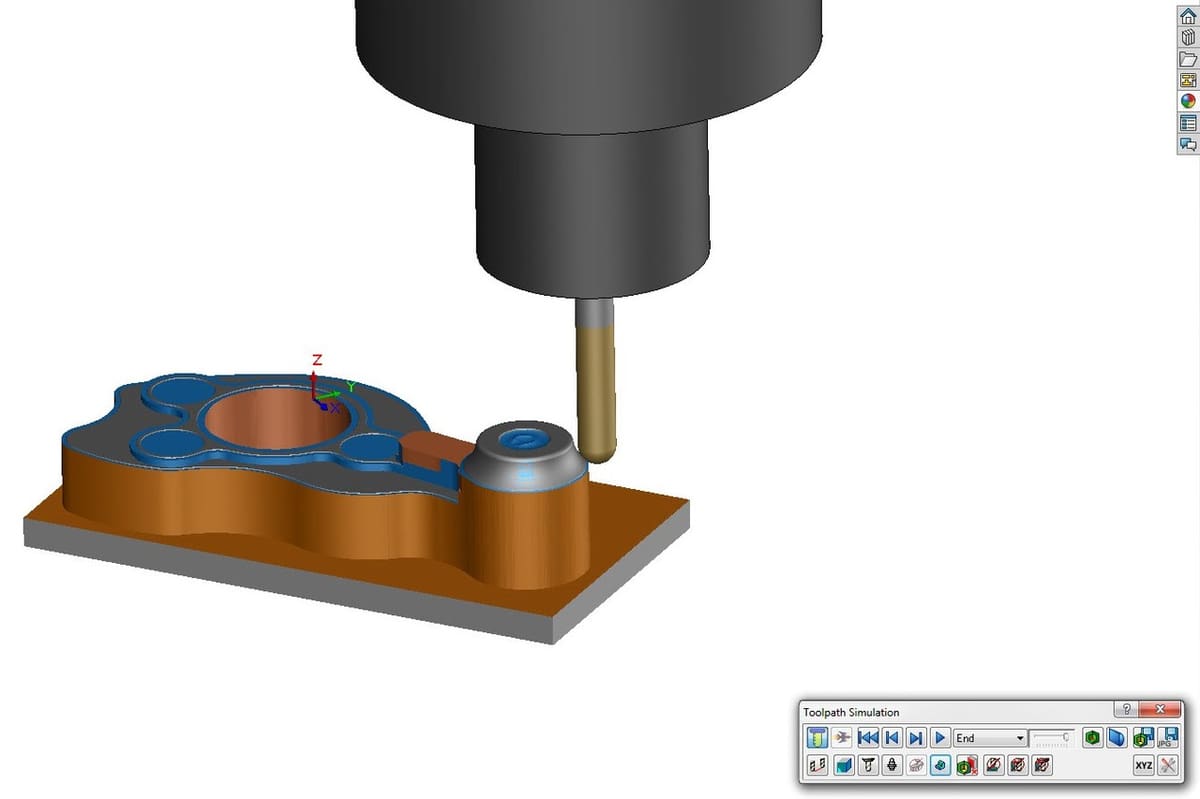
- Toolpath generation: The toolpath is a set of given coordinates that the machine is required to follow during the machining process. A good example would be setting a cutting sequence.
- Device configuration: Before operation can begin, machine parameters like voltage, cutting speed, and pierce height must be adjusted. Different programs can set different parameters, but once these parameters are defined automatically, the machine operator’s job will be simplified.
- Optimization: In consideration of all of these details, CAM software attempts to identify the best orientation to maximize efficiency.
Once a designer is satisfied with the design, the CAM software will send all of the above information to the CNC machine to physically produce the part. CNC machines are able to read and understand the numerical code, which is normally converted to electrical signals.
Relationship Between CAM & CAD
One rarely talks about CAM software without touching on computer-aided design (CAD) software; the two go hand-in-hand.
CAD software enables architects to make 2D drawings and 3D models. It focuses on how the product will look and how it will function, while CAM software focuses on how to make it. In a nutshell, CAM software closes the gap between design and manufacturing by enabling the accurate realization of the models, drawings, and designs, outputting the necessary G-code used by the appropriate machines.
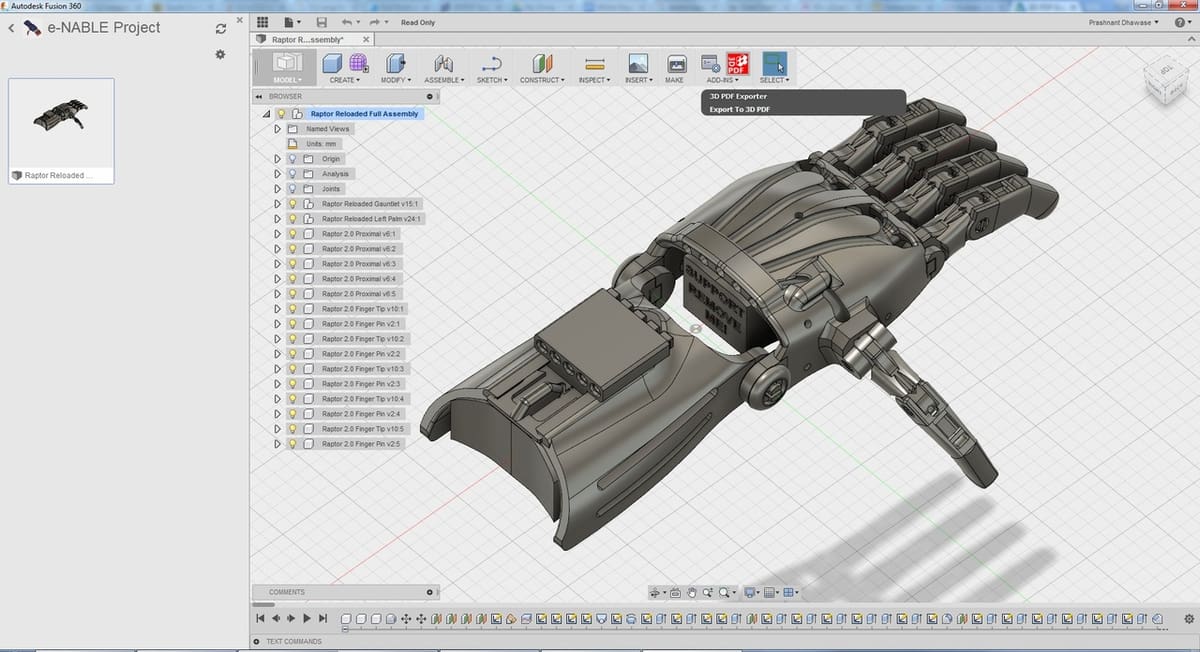
Typically, once a (production-destined) design is complete in CAD, it needs to be imported into CAM software. Then again, some tools, like Fusion 360, have both CAD and CAM properties. The integration of CAD and CAM into a single platform enables designing and manufacturing using the same system of encoding geometrical data. This linkage significantly shortens the design and manufacturing period as well as expands the scope of production. The existence of such tools is also probably why the terms “CAD” and “CAM” are sometimes used interchangeably.
The Benefits of CAM Software
CAM software brings several benefits when creating components, especially when compared to manually operating machines:
- Efficiency: Prepping a design for automated production means zero breaks between maneuvers.
- Accuracy and consistency: Multiples of the same complex component will be made in exactly the same way, ensuring that they are identical.
- High production speed: CAM allows for high-speed machine tool paths, making it possible to produce parts faster.
- Precision: Parts can be intricate. Even circuit boards are possible when designs are prepared with CAM software.
- Minimal waste: Automation and optimization algorithms allow operators to know exactly how much material is necessary.
Which CAM Software to Use?
The CAM software of choice will depend not only on the design, but also on the design software you are using. Three major categories of CAM software exist: CAD/CAM software, independent CAM software, and CAM plugins for design programs:
1. CAD/CAM Software
Some CAM tools come packaged with CAD suites, meaning a single program will have both CAM and CAD capabilities. Essentially, the tool paths will be linked back to the designing program, meaning that any change on the design will be immediately mirrored in the CAM program.
For this kind of tool, the CAD file does not have to be re-imported into a separate CAM software, which eliminates the need to reprogram the toolpaths. However, the biggest downfall with this tool is that it usually has very basic CAM operations and cannot be used to create highly-detailed parts.
Fusion 360 is a perfect example of a tool with both CAM/CAD tool.
2. Independent CAM Software
This type of tool generally has powerful CAM capabilities and can be used to create complex geometries. However, it can pose a challenge if the CAD file cannot be imported into it.
Therefore, before you opt for a stand-alone CAM software, you must make sure it is compatible with your CAD program.
Also, when using a stand-alone CAM software, you must keep in mind that altering the design in any way will mean having to go back to the designing tool to create tool paths for the CAM program afresh.
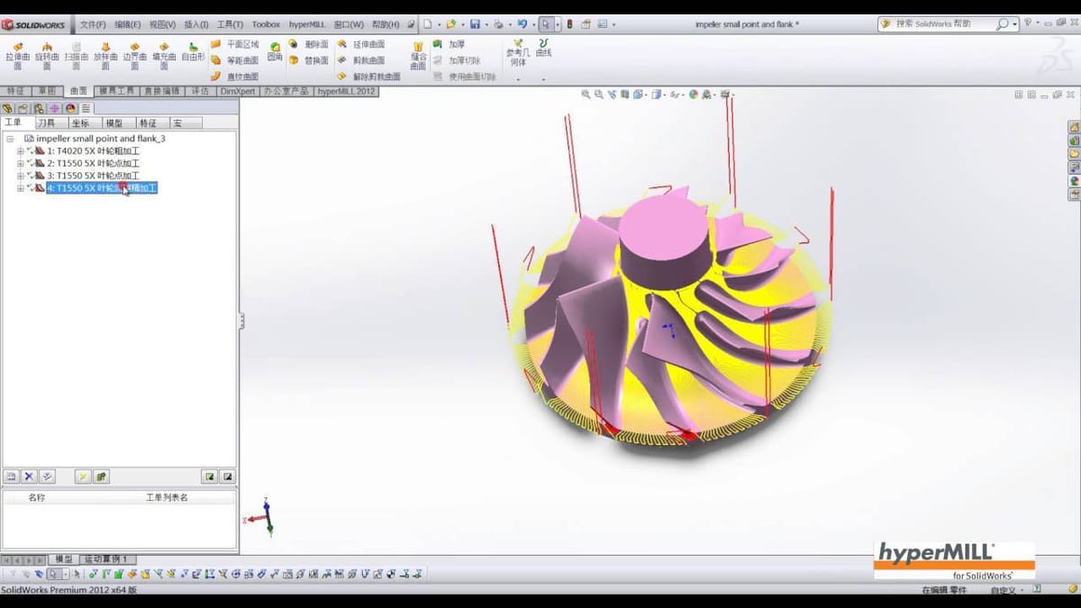
hyperMill is an example of a stand-alone CAM software.
3. CAM plugins for CAD programs
There are also CAM plugins that can allow a designer to create tool paths from within the CAD program they are using to design their parts. For example, HSM is a CAM software plugin that can integrate into SolidWorks or Inventor.
hyperMill, on the other hand, is available both as a stand-alone tool and a plugin for SolidWorks, Inventor, and hyperCAD-S. SprutCAM also has plugins for CAD programs like SolidWorks, AutoCAD, Rhinoceros, and Inventor.
Feature image source: neter cadx / YouTube
License: The text of "CAM Software – What Is It & What Does It Do?" by All3DP Pro is licensed under a Creative Commons Attribution 4.0 International License.