CATIA vs SolidWorks: The Differences

It's a parametric design and engineering showdown: CATIA vs. SolidWorks. Read on for all the specs and decide which is best for you!
In the professional solid modeling space, CATIA and SolidWorks are two software kingpins that come from the same company: Dassault Systèmes.
CATIA (Computer-Aided Three-Dimensional Interactive Application) was first launched in 1982, while SolidWorks dates back to 1995. Even though CATIA is older, in today’s market, both programs are equally established and popular, with SolidWorks even pulling a little ahead in recent years. This is because SolidWorks has an overall friendlier UI, is more affordable, and is better suited for independent work, whereas CATIA is geared toward collaborative work.
Both programs are aimed at computer-aided design (CAD) and computer-aided engineering (CAE). However, CATIA also has a product lifecycle management (PLM) suite and is considered the software par excellence for such functionality.
CATIA and SolidWorks are mainly used for applications in 3D surface and solid modeling, fluid and electronic systems design, consumer electronics design, mechanical engineering, structural design, and 3D modeling for 3D printing.
In the following, we’ll go into more detail regarding what makes CATIA and SolidWorks different, from hardware requirements to features and use cases. One note before we dive in: The versions discussed in this article are CATIA V5 and SolidWorks 2022. There is a CATIA V6, but the most popular version remains V5, which has been updated annually since 2006. Outside of pricing, the below information is also valid for V6.

Prices & Licensing
Dassault Systèmes has a very specific purchasing scheme that seems consistent across different products. They don’t sell their products directly through a webpage but use an authorized value-added reseller (VAR). So prices might differ slightly according to your country and the deals offered by a particular VAR.
Nevertheless, there is an established approximate price range for each program. Additionally, both SolidWorks and CATIA currently have 3D Experience options. 3D Experience is a Dassault Systèmes business platform that allows companies to synchronize design with other business aspects, such as materials, quotations, licenses, and feedback. The platform has had some mixed reviews from users, and if that’s a concern, you can always acquire only the traditional software.
CATIA
CATIA has a total of 108 Workbenches, which are sets of toolbars and menu options for a specific application. They include Architecture, Product Design, Weld-design, and more.
- Complete version: For the complete version of CATIA, you can choose from one of the following.
- Perpetual license: around $11,200 plus $2,000 of yearly maintenance
- Annual license: around $4,500
- Quarterly license (every three months): around $1,700
- Trial version: Strictly speaking, CATIA doesn’t have a trial version. In its place, it has a 3D Innovator, a web-based emulator where you can try CATIA for free for 30 days.
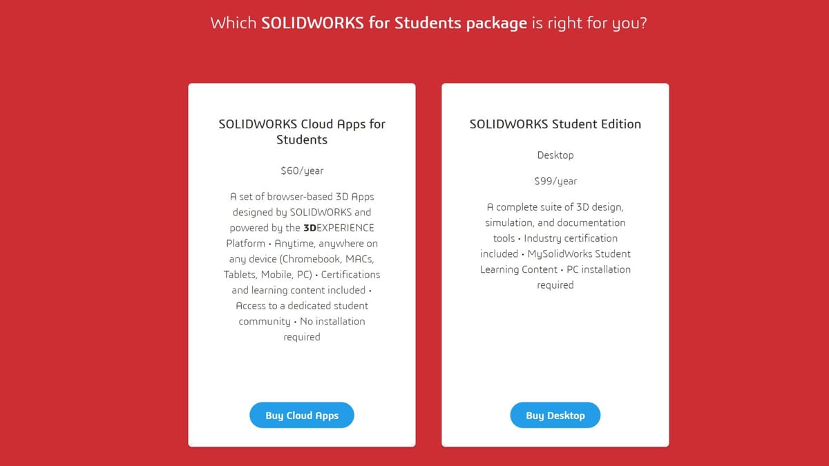
- Student version: You can get the CATIA student edition for free by contacting your education institution directly. This results in a student license for the CATIA student edition. You can also get the CATIA student version on your own at a discounted price, which includes 3D Experience CATIA for Students as well as online education and certifications, all for $60 per year.
- Custom version: It’s possible to buy Workbenches depending on the specific functionalities you need. Many companies go this route to avoid paying for functions they’d never use. A perpetual license starts at $2,700, but the price may vary according to the set of Workbenches you want or deals your company gets.
SolidWorks
SolidWorks is a little bit more straightforward, although you still need to purchase it directly with a VAR.
- Basic version: SolidWorks’ core functionality can be updated in two ways.
- Perpetual license: This costs around $4,000 and is only valid for the same version, without upgrades. This means that, for example, if you buy a perpetual license for SolidWorks 2017, you can only use that version until you purchase a more recent one.
- Annual license: One can purchase a license for around $1,300 per year with the possibility to update to the most recent version the following year. You get the installation files and a license key with a lifespan of one year. After the license key expires, you will need to buy a new one for either the same version or a newer one. This isn’t really subscription-based, as it doesn’t renew automatically, but it has the advantages of being cheaper in the short term and comes with the ability to upgrade.
- Professional version: Includes Basic + SolidWorks PDM Standard, CircuitWorks for electrical CAD, the toolbox of standard parts, and Visualize for advanced rendering. The price is around $5,500 for a perpetual license or $1,500 annually.
- Premium version: Includes SolidWorks Professional + linear stress analysis, piping and tubing design tools, and time-based motion analysis. This costs around $8,000 for a perpetual license or $2,000 for an annual one.
- Free version: You can also get an online trial version, but you’ll need to sign up for MySolidWorks. Know that nothing you create here can be saved.
- Student version: Similar to CATIA, you can get an education license for free from your academic institution if they have purchased the SolidWorks student edition.
System Requirements
Since both CATIA and SolidWorks work with heavy graphics and are both coming from Dassault Systèmes, they have similar performance styles. They require strong computer performance to avoid crashes and lagging. Additionally, both programs need a three-button mouse with a scroll wheel. Finally, either option is only available for Windows, with no support for Mac or Linux.
CATIA
- OS: Windows 7 or 10 64-bit; support for Windows 11 has yet to be announced
- Processor: 64-bit Intel i5 or better
- Memory: Minimum of 4 GB of RAM; recommended 8 GB or more
- Graphics: Graphics card beneficial but not necessary
- Storage: Minimum of 10 GB of free disk space; more is recommended for smooth operation
- Additional software: Microsoft Office 2013 or newer, especially Excel, is necessary to generate reports or BOMs
SolidWorks
- OS: Windows 10 or newer; from SolidWorks 2022 and onwards, older versions of Windows are also supported
- Processor: 64-bit Intel or AMD; processors as low as Intel Core i5 should work
- Memory: Minimum of 16 GB of RAM; recommended 32 GB or more
- Graphics: Graphics card beneficial but not necessary; most processing is done via the CPU unless otherwise configured
- Storage: Minimum of 22 GB of free disk space; more is recommended for smooth operation; SSD highly recommended
- Additional software: Microsoft Office 2016 or newer, especially Excel, is necessary to generate reports or BOMs; 2016 and 2019 won’t be sufficient after SolidWorks 2023
Interestingly, although CATIA is the overall more capable software, its hardware requirements are generally lower than those of SolidWorks. This is mainly because SolidWorks puts more effort into producing nicer design renders during modeling.
UI & Layout
CATIA and SolidWorks share similar capabilities, although the organization is different. For example, you can find every one of CATIA’s tools inside the desktop application. For SolidWorks, you have to open the appropriate application. For example, to use electrical tools, one would use SolidWorks Electrical, which is its own application.
Within its single application, CATIA is organized in Workspaces. For example, the Part Design Workspace is separate from the Sheet Metal Workspace. In contrast, the main SolidWorks application has three workspaces for Part, Assembly, and Drafting. Inside the same Part workspace, you can find the Part Design tools and the Sheet Metal tools organized in tabs.
Another similarity between the two programs is that they both use a tree that lists all present elements. (It’s called simply Tree in CATIA’s case, and Feature Manager Design Tree in SolidWorks’ case.) This includes origin points, coordinate systems, planes, and operations. In CATIA, the tree hovers in a transparent background on the left of the Viewport. In SolidWorks, it’s contained in a box to the left of the Viewport. SolidWorks’ tree provides more functions than CATIA’s, as it has tabs with additional information about configurations, materials, and more.
SolidWorks and CATIA operate with a similar design workflow. You select a plane, create a sketch, perform an operation based on that sketch, and repeat until the design is complete. If you’re switching from one to the other, the modus operandi is very intuitive.
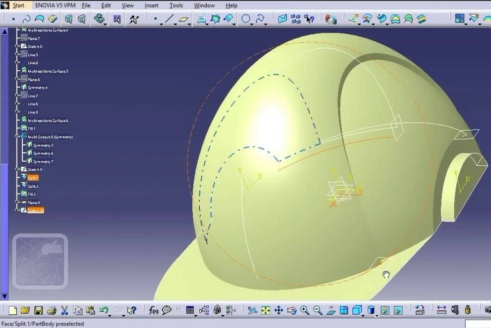
UI: CATIA
Since Catia has so many capabilities, the first step when you start is to tell the program what you’ll be using it for, as this will affect the tools displayed. In this article, we’ll focus on mechanical design, which is CATIA’s most popular application.
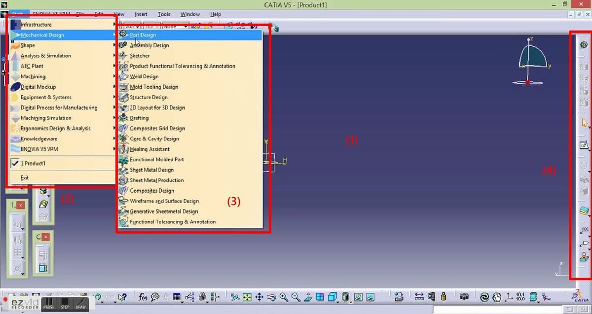
When you open CATIA, most of what occupies the screen is the Viewport (1), where you see the origin point, the coordinate system, and some tools.
Environments
You’ll find the Menu Bar on the topmost part of the screen. From the very important Start tab, you can open the environment (2) tools for Infrastructure, Mechanical Design, Simulation, Machining, Ergonomics Design and Analysis, and more.
Inside these environments, there are even more specific options. This is where you have to pick the Workspace to open (3). (Workspaces can be thought of as sub-environments). For example, for Mechanical Design, you have Part Design, Assembly Design, Weld Design, Functional Molded Part, and Sheet Metal Design, among others.
Design Tools
The Part Design Workspace is where most of the work happens, at least in the early stages of using the program.
You can find the Design Tools (4) to the right of the viewport in CATIA. These include tools for sketching, among other things, lines, rectangles, circles, and splines. There are also tools for selecting planes and tools for extruding operations. This menu is definitely more simplified than the SolidWorks menu, which can make it less overwhelming at the start. However, SolidWorks’s menu has more visual aids to understand the tools.
Context Menus
CATIA depends on context windows that open when accessing a specific function. You have to be inside a tool to find more information on it, which means you might not notice many essential tools early-on. For example, you need to start a sketch to access the sketching tools. When you’re working on a “Pad,” which is the equivalent of extruding a boss or base in SolidWorks, a Pad Definition window pops up with information about depth and sketch.
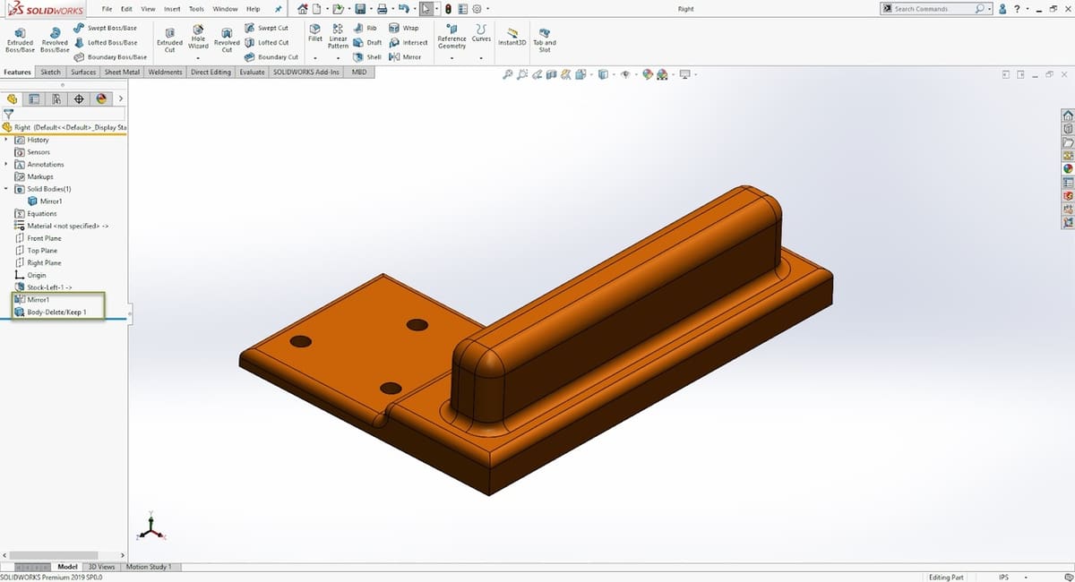
UI: SolidWorks
The SolidWorks desktop application reads “SolidWorks 2022” (or the equivalent year’s version). This is the main option used, since it includes the functions for mechanical modeling. The main functions include Visualize, Electronics, and PDM, all of which have their own desktop application. They can be installed or bought separately, or purchased as part of a package. For example, with a student license, you get access to all of them, but with SolidWorks Standard, you can’t access Simulation.
Different Desktop Applications
To access more complex tools, like SolidWorks Visualize for high-quality renderings or SolidWorks Electrical for electric diagrams and simulation, you need to open an entirely new program. There’s also SolidWorks Composer to create documentation. These are all different SolidWorks applications that require their own activation key, which is where the package plans (Basic, Premium, Professional) come into play.
Environments
When you open SolidWorks, there are three environments to choose from: Part, Assembly, and Drafting. (Note that these aren’t explicitly called environments by SolidWorks.) You start by selecting the environment you want to work in when creating a new document. These environments are inherent to the file type, so if you open a SolidWorks Drawing file, it will open in the Drafting environment by default. To Switch between environments, switch the file type to open.
Command Manager
Inside the above environments, you can access many tools (e.g. for rendering) organized in tabs. You can find full Sheet Metal and Injection Molding capabilities in their own tabs. Some tabs include Sketch, Features, Surfaces, Sheet Metal, and Evaluate. In this last one, you can measure dimensions or get physical data like volume, density, or weight.
In contrast to CATIA, SolidWorks has all the modeling tools on the Command Manager on top of the Viewport. You also have the three planes and origin point on the Viewport. Even if they’re hidden, you can find them in the Feature Manager Design Tree.
The Feature Manager Design Tree has tabs for Configurations (which are different versions of a part or assembly stored inside the same file), Appearances, and Material.
Context Menus
In SolidWorks, when a context menu needs to open, for example to specify the depth of an extrusion, the menu will replace the Feature Manager Design Tree and hover over the viewport. This stands in contrast to CATIA, where context menus open in a new window.
Features & Functions
As mentioned above, SolidWorks is fundamentally 3D CAD software, while CATIA is CAD and PLM software. CATIA can therefore do everything SolidWorks can and more, but there’s a catch.
When it comes to Mechanical Design, SolidWorks’ tools are stronger and more optimized, and many steps of the workflow are omitted. In contrast, when it comes to industry plant design or architectural and structural design, CATIA takes the cake with regard to tools, documentation, and most importantly, stability. SolidWorks can also handle these tasks, but it’s much slower performance-wise and requires more steps.
Features: CATIA
As was established previously, CATIA is organized in Workbenches, and its installation packages are usually custom-built for large companies, providing exactly the tools they need. The strongest and most popular Workbenches include Wireframe and Surface Design, Analysis and Simulation, AEC (Architecture, Engineering, and Construction), Equipment and Systems, and Mechanical Design.
Mechanical Design
The Mechanical Design Workbench does as the name indicates, and it’s where you’ll find all the traditional 3D CAD modeling tools. This is the Workbench most similar to SolidWorks, and its modus operandi works similarly. It has tools for sketching, extruding, cutting, creating round corners and bevels, and more.
Surface Modeling
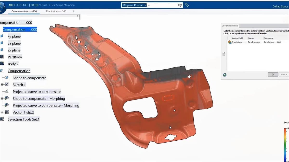
CATIA’s surface modeling tools are far superior to SolidWorks’, although the latter has improved greatly in recent years. CATIA’s surface modeling tools are located in the Wireframe and Surface Design Workbench. It allows you to create wireframe construction elements from scratch, or add on top of existing models, to enhance or add certain characteristics. It’s therefore useful during both the conception and final-details stage.
Analysis and Simulation
This Workbench includes modules for different kinds of analysis you can run, and the modules you have access to would depend on the plan bought. The complete range of modules includes Nonlinear Structural Analysis, Thermal Analysis, Generative Structural Analysis (for parts and assemblies), Generative Dynamic Response Analysis, and FEM (Finite Elements Method) for Surface and Solid.
AEC
The AEC Workbench includes features for the whole complete pipeline. It’s quite impressive, from terrain analysis and preparation procedures to civil work, structural design, façade design, and construction process planning. It’s so complex it has its own separate YouTube channel to explain and showcase features.
Equipment and Systems
Working in both 2D and 3D, this environment allows the user to create and control mock-up simulations. It combines programming, electronic, pneumatic, hydraulic, and mechanical equipment to examine and plan the interactions.
Features: SolidWorks
As mentioned, SolidWorks has an advantage when it comes to mechanical design. Let’s talk about the tools that make that possible.
Personalized Mouse Gestures
SolidWorks allows you to use mouse gestures to increase workflow speed and efficiency. For example, you can right-click and slide up to add a mate or to edit a sketch. You can choose what each motion does from SolidWorks 2019 and onwards, and there are up to eight mouse gestures.
Keyboard Shortcuts
Most SolidWorks keyboard shortcuts focus on views, as tools are usually handled with the mouse. You can use the numpad to change the view type or press the space bar to select the view mode. Alternatively, the shortcut ‘S’ opens a hover context menu, which you can also personalize to quickly access weldment symbols in the Drafting environment.
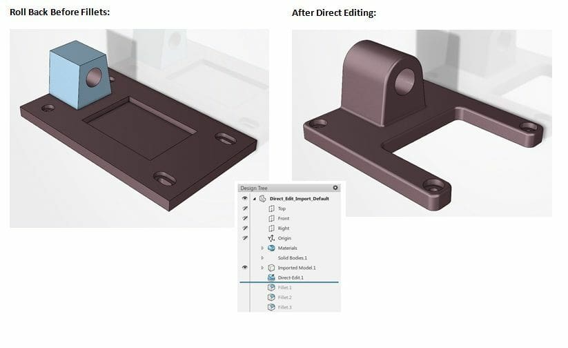
History-Based Modeling
One of the most powerful and marketable characteristics of SolidWorks is the modeling. Every operation done on a part is stored in the Featured Manager Design Tree in chronological order. It’s possible to suppress operations or go to back in time and add or modify previous steps. This makes it great for the conception process, where one typically makes more changes.
Multi-Solid Parts
This is another characteristic that makes SolidWorks such a strong contender. You may have one SolidWorks Part file, but this part could actually contain two or more solids. This is useful if, for example, you choose not to fuse a resulting shape or if you’re working with Sheet Metal. The feature is therefore commonly used in surface modeling, sheet metal, and designing symmetric parts.
Environments
As previously mentioned, when you open the SolidWorks application, there are three environments to choose from with an inherent file type linked to them. These are Part, Assembly, and Drafting. Inside the Part environment, you can access Sheet Metal, Injection Molding, and Surface Modeling. In Part and Assembly, you can access simple rendering tools. And in all three environments, you can use Evaluate tools. These tools are found in the command manager and can be added or hidden by right-clicking on the tabs.
Use Cases & Applications
SolidWorks and CATIA are both aimed at engineering, so they share many applications. They’re also from the same company, making it easy to check their use cases in the Dassault Systèmes Customer Stories portal. Just note that even though they share applications, the intentions may be different. It’s commonly said that SolidWorks can be used to design a car, while CATIA can be used to design the factory where the car is made.
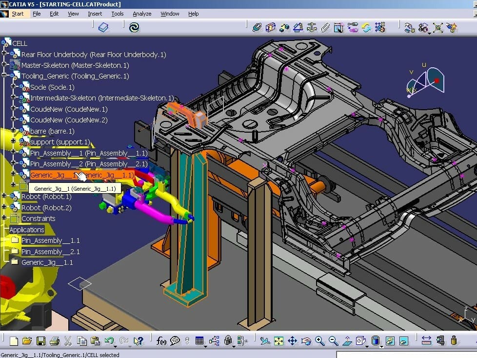
Another important note is that, even though SolidWorks looks more modern and CATIA more retro, the latter is much more stable when handling large files.
CATIA
Many companies use CATIA for their design processes. For example, it’s been used for product design by Kindof, which creates furniture and takes advantage of CATIA’s cloud storage. Meanwhile, Branch Technology uses the program to design and plan the manufacture of buildings’ façades. It’s even used in the transport industry, with the start-up TransPod attempting to develop magnetic hovering trains.
These examples show that CATIA covers a wide range of applications, including product design, architecture, engineering, and manufacturing planning.
SolidWorks
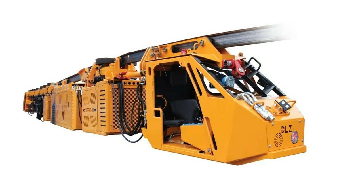
SolidWorks is mainly used for machinery design, usually on a large scale, down to the smallest details, as seen by the Czech mining company, Ferrit. They use SolidWorks to design and get a complete view of their newest generation of Mining Trainkarts. Yet, SolidWorks also applies to consumer product design and surface modeling. For example, Simple Energy used SolidWorks to design its version of an electric scooter. Companies in the transport and maritime areas, like Sunreef Yachts, also use SolidWorks to design ships and explore new optimized shapes.
SolidWorks’ most popular applications include mechanical engineering design, product design, surface modeling, and even documentation, using SolidWorks Composer.
Company & Community Support
As both SolidWorks and CATIA come from Dassault Systèmes, they have similar company support. Regrettably, that company support isn’t easy to navigate, typically being typically slow and hard to reach. If you need support, you usually have to contact your reseller.
That said, the company does have active YouTube accounts, where it shares detailed explanations of updates. Sometimes, there are also seminars teaching advanced features of their programs. In general, CATIA has less presence, so in that sense, resources, communities, and free information are harder to come by.
CATIA
- Company support: You can get CATIA community news and support in the 3D Experience portal, for which you need a login. The company also offers live and on-demand virtual seminars, called e-Seminars, covering specific features of CATIA. Apart from the 3D Experience Education network, you can learn through the official YouTube channel, where the company shares patch notes, success stories, and more e-Seminars. Lastly, there’s the Dassault Systèmes hotline.
- Community support: For unofficial communities, there’s the Reddit group, which is much smaller than the SolidWorks subreddit. (CATIA’s has 2,500, while SolidWorks’ has 47,800 members.) Yet, CATIA users may be more active in 3DCAD Forums.
SolidWorks
- Company support: Similar to CATIA, there is a hotline for Customer Support as well as a Support Page for tips and tutorials. Keep in mind, for this last one, you need a SolidWorks customer login. As mentioned, the YouTube channel is the best pool of official information, and it’s regularly updated with new content.
- Community support: SolidWorks also has a Reddit group, where people post troubleshooting questions, design challenges, and cool projects. GrabCAD, a collaboration platform from Stratasys, offers an online community where you can check out free designs and interact with other members. It’s a great resource for seeing what can be done, getting some models, and finding answers to your questions.
License: The text of "CATIA vs SolidWorks: The Differences" by All3DP Pro is licensed under a Creative Commons Attribution 4.0 International License.