
Chitubox Tutorial: Hands-On Tutorial to Get Started

Chitubox is among the most famous slicers for resin-based 3D printing. Check out our Chitubox tutorial to learn all about it!
3D printing has become more common and accessible, with people being exposed to different additive manufacturing technologies for both professional and hobbyist or maker goals.
Having a great design or model and a great 3D printer doesn’t automatically imply a perfect outcome. While the printers involved may have heightened abilities, such as maximum speed and precision, the technology involved influences the use case, design thought process, and printing outcome.
The right slicer is important to optimize the printing process and results, and when it comes to resin 3D printing, Chitubox is a popular choice – and for good reason.
In this article, we’ll look into how to slice a silicon mold in Chitubox. While we’ll dive straight into optimizing the design in Chitubox for 3D printing, you can also check out our introductory article on the program, especially if you’re just learning about it and need to get your bearings.
We’ll start by selecting the printer of choice and then we’ll upload a model, manipulate it, and tweak the settings to obtain the desired results. We will conclude by exporting the sliced model for printing, then take a few moments to address some tips and tricks.
Let’s get right into it!

Slicing Tutorial
Getting Started
Once you’ve downloaded, installed, and got the program running, you can change some of its default settings. Under the main menu (three horizontal lines on the top left), you can choose “Settings” and change the appearance, file aspects, and system configuration, to name a few.
For this tutorial, go to “Settings > Function”, then check the “Preview Support (Add Support)” box to enable it. Feel free to play around with other settings for your setup.
When the settings are to your liking, it’s time to select the 3D printer. Chitubox allows the creation of custom printer profiles if yours isn’t listed by default.
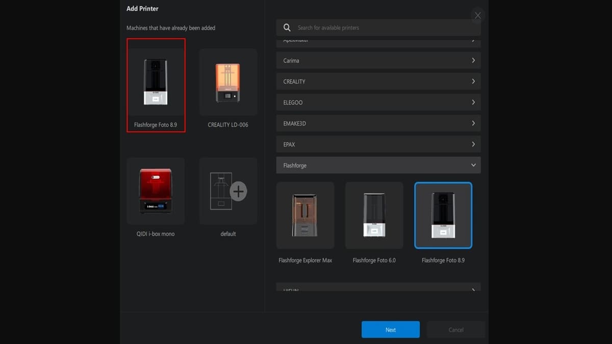
If you’re opening the slicer for the first time or no machine has been previously selected, you will be prompted to choose one. For our tutorial, we’ve selected the FlashForge Foto 8.9. If your setup includes a different machine, you can navigate to the lower-left corner and click the ‘+’ icon on the machine bar, which should read “Add New Machine” when you hover over it. Then you can look for the brand from the available list or you can type it in the search bar.
Once you’ve found your machine, you can make any necessary changes before adding it to the setup, if you’ve changed the hardware in any way.
If your specific 3D printer doesn’t have a default profile, you can go through the same steps as above. After selecting a similar machine to yours (for example, in size), click “Next”. From the Configuration menu that will appear, you can change its name (by typing however you want to reference it), the type of mirror, the resolution and size, and the rest of the settings available for it. Finally, click “Apply”, and the new machine tab should appear on the bottom left of the UI.
With your hardware set up in the slicer, it’s time to look at the model.
Loading & Orienting the Model
With the 3D printer selected, it’s time to import the model.
- Click “Open” (orange box).
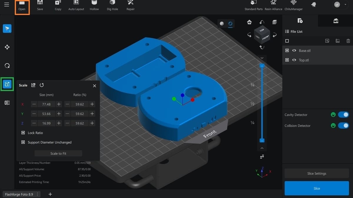
- Navigate to the desired location and select the model to be loaded into the slicer. In our case, we’ll import the top and base of the mold (saved in STL format).The model will appear on the build plate, as seen above.
- If applicable, you can reduce the model’s size by left-clicking on the scale button on the side bar (green). The “Scale to Fit ” command will help you scale the model to fit the bed size automatically.
A key feature of Vat polymerization 3D printing machines (like SLA and DLP) is their flexibility to print parts in two directions: either bottom-up or top-down. Our selected machine is a bottom-up one; this will inform our action in the next section.
Model Placement & Orientation
Unlike top-down printers, bottom-up machines have a more complex approach for printing to be successful. We need to orient our imported model so that the support (almost always a necessity), can hold the model in position during the process.
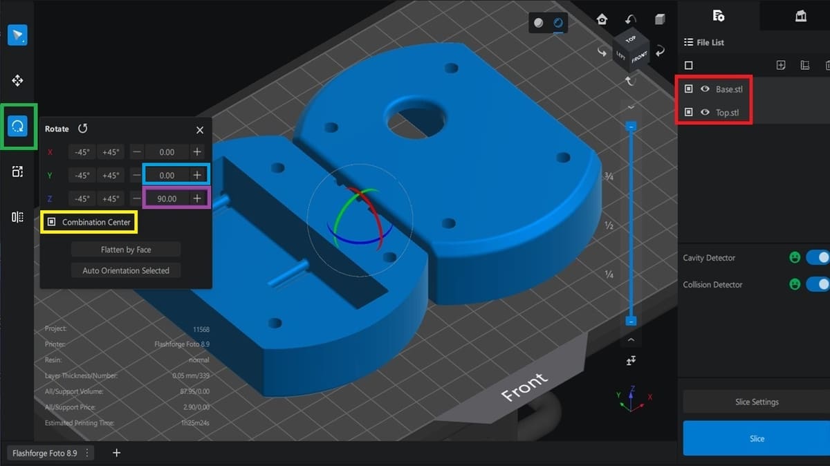
Let’s orient the part in a few steps. Firstly, we need to align the mold so that its longest axis is parallel with the front of our machine. Here’s how to do it:
- Select the top and base mold from the “File list” (red).
- Click on the “rotate” function on the side bar (green) and then input “90” degrees for the Z-axis (purple).
- Ensure that “combination center” (yellow) is checked as shown, so that this rotation can be implemented from the center of the molds.
Note that our base and top molds have different sides facing the print bed. We’ll change this to avoid multiple steps for getting the right orientation. To do this, rotate the base via the Y-axis manipulator and input “180” in the dialogue box (light blue). The back of the base mold should be facing up, just like that of the top mold (see image below).
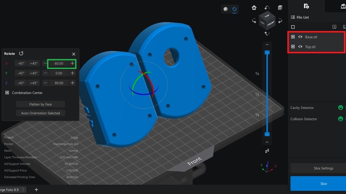
Next, we need to reduce the cross-sectional area of each layer of our mold. This will lower the force the part will be subjected to during peeling (a separation of the cured layer from the base of the vat).
- Select both models (red).
- Rotate them along the X-axis by inputting “60” degrees (green).
Your mold will be oriented as shown above.
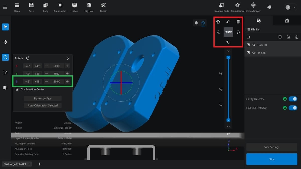
We’ll further manage the molds so that the enclosed cavities aren’t facing the vat (resin tank). This is to reduce failures associated with hollow sections. Here’s how to do this:
- Rotate both molds via the Z-axis, 30 degrees, as done previously (green).
- When viewing the model from the front view (red), it will reveal the magnitude of the turn (slanting).
Note that this “30” degree turn will override the “90” degree we did earlier, but this workflow is necessary so that we can accurately judge the magnitude of the turn (if its adequate).
As mentioned, it’s more than likely that you’ll be using supports. Before we look into how to apply them, we will look at how to hollow the model and add drainage holes.
Hollowing & Hole Digging
Unless you need a very strong and resilient model, resin prints are usually printed hollow to avoid issues with uncured resin and to reduce material use and printing time. Large flat areas on a model will create strong suction to the FEP film (the transparent vat sheet), leading to print failures. Hollowing reduces this risk, and it can be done in a few, simple steps:
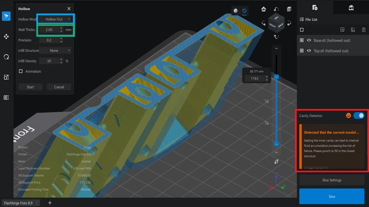
- Select the model and choose “Hollow” from the top menu.
- Select the type of “Hollow Mode” from the menu that will pop up: either “Hollow Out” or “Peel” (light blue). The former allows you to set an infill, while the latter doesn’t.
- Adjust the wall thickness to balance strength and resin use (green). For our silicone mold, a slightly thicker wall (around 2-3 mm) would make the parts durable for the intended use.
It should be noted that hollowing the model requires holes for the resin to be drained. You can see the error message informing that holes are necessary (red).
Hole Digging
As pointed out in the error message, we need to prevent inner fluid accumulation by punching a hole in the surface of the mold for the resin to be drained out through. The best placement of the hole(s) is based on human judgement.
However, for the hole placement, a good rule of thumb is to add drainage holes at the lowest points of the model – which is what we’ve done in our case. Depending on the size of the print, you might also want to add drainage holes where they might be hidden or easily covered in post-processing, and a final one at the highest point can also be helpful.
Adding drainage holes is pretty straightforward.
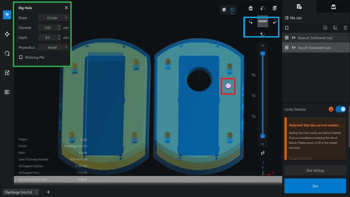
- Select the model and click on “Dig Hole” from the top menu.
- From the menu that will appear (green), chose the hole’s shape (circular, hexagon, or square), adjust its diameter and depth, and decide whether you want it to be perpendicular to the model or to the screen.
- Use the view cube (light blue) to try different angles and choose the most convenient places for the holes.
- Should there be any issues with the location or size of the hole, a warning message will appear letting you know so.
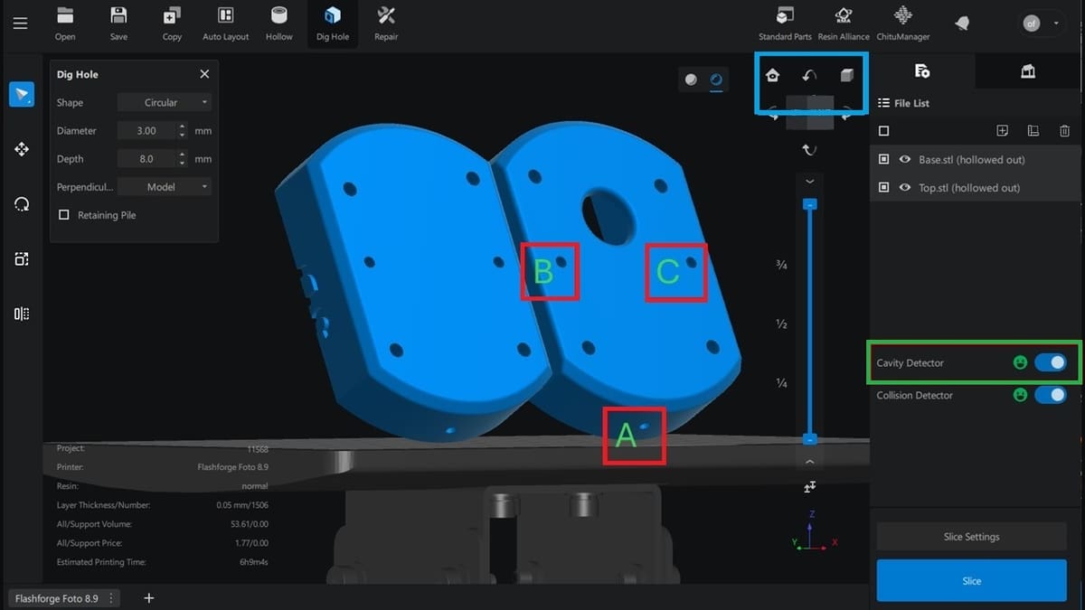
Note that, in our case, we can’t afford to have holes inside the mold’s cavity, so we dug a hole on the back of the model (A, B, C). This will take care of the pressure differences that can lead to failure, when the cured area tries to separate from the vat base.
Depending on the specifics of your model and its intended use, you may not need to worry too much about the holes. During post-processing (or after curing), you can add epoxy (or any non-reactive glue) to a drain hole to cover it (if need be).
In our case, because we’re not interested in the aesthetics or surface of the external part, as long as our drain hole doesn’t puncture or contribute to the failure of the inside cavity, we should be fine.
As mentioned, you can use the arrows and view cube (light blue) to navigate the different sides of the model, and the “Cavity Detector” feature (green) will show a happy face (and no additional warning messages) when everything’s good. You can also toggle off such automated help.
With hollowing and drainage holes out of the way, it’s time to add supports.
Adding Support
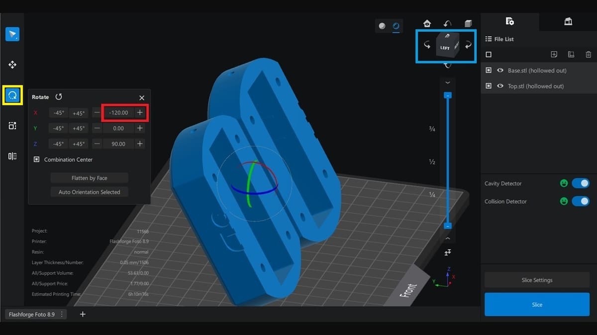
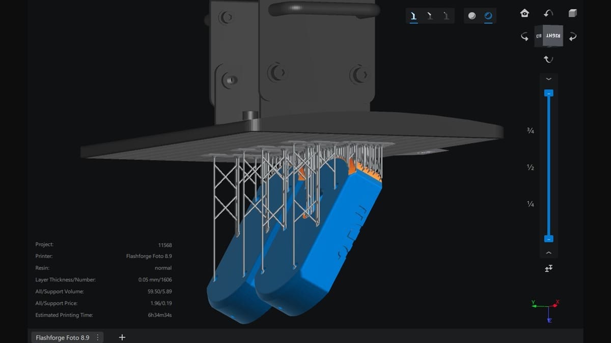
While supports are mostly unavoidable, we want to avoid having such structures in the functional area of the mold (the cavity). However, this can’t be achieved with our current orientation of our mold, as the support will be propagated towards the cavity. To correct this, we’ll need to invert the orientation as shown above:
- Select the model.
- Select the rotate tool (yellow).
- Change the degrees on the X-axis to -120 (red).
Interestingly, the molds are still tilted by 60 degrees, as before. However, they are now in the opposite direction.
With the correct orientation, it’s time to add supports:
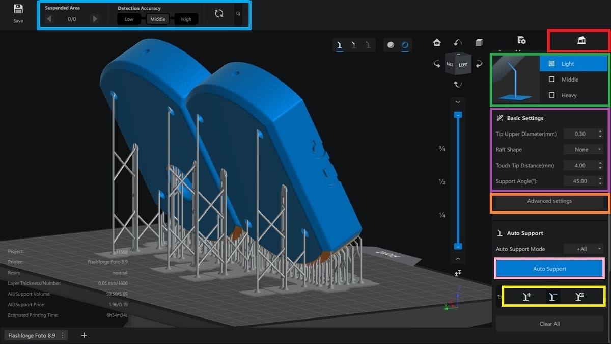
- Click on the “Support Tab” (red) to launch the supports panel. For the purpose of this tutorial, the Detection Accuracy (light blue) is set to “Middle” (average).
- Select the width of support you want (e.g. “Light”, “Middle”, or “Heavy”) – in our example, we opted for “Light” (green).
- Adjust the support’s basic settings as needed (purple), although the default ones should work for the most part (unless there’s something especially complex about the model). Here you can decide on the diameter and distance of the touching tip, whether a raft shape is included or not, and the support’s angle.
- If needed (and you know your way around the details enough), you can work on advanced settings (orange) and further tweak the top, middle, and bottom of the support structures, as well as the raft (if you’ve enabled it).
You can use the support manipulation tool (yellow) to add, move, or remove support branches. You can also “Clear All” the supports by clicking on the corresponding button below them. And finally, you can opt for the “Auto Support” button (pink) to generate the structures automatically.
Once you’re done setting the support structures to your liking, you can click on the slicing tab (next to the “Support Tab” from step 1).
Resin & Print Settings
Once back in the main menu, click on “Slice Settings” (above the “Slice” button). Here you can adjust the machine, resin, and print settings, as well as some advanced options.
Because the printer we selected has a preset profile, we don’t need to make any changes; we’ll leave the default settings active. However, we can easily tweak other settings as follows:
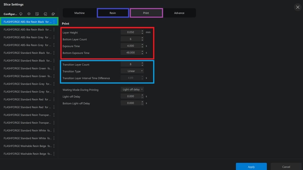
- Resin selection: Since we’re slicing a silicon mold, ABS-like resin fits our intended use. To confirm the choice, click on the specific resin you want. In our example, we chose “FLASHFORGE ABS-like Resin Black for 0.05 mm” (green). If you click on a variety of options, you’ll see the print settings change (under the “Resin” tab, blue).
- Layer Height: We will adopt a layer height of 0.05 mm to achieve a smooth surface finish and to match the resin’s features. From the “Print” tab (purple), verify that the value is set to 0.05 mm (red).
- Bottom Layer count: While a minimum of five bottom layers is recommended, we’ll increase this to six to enable a stronger foundation and prevent adhesion problems (red).
- Exposure Time: ABS-like resins typically require longer exposure times than standard resins. The resin manufacturer’s guideline is always the ideal value, so it’s always useful to check them. However, the default setting should work just fine (as they were set with the specific material profile) (red).
- Bottom Exposure Time: This will ensure proper curing of the initial layers, and it’s recommended to be 8–12 times higher than the normal count. We will leave the default setting for this (red).
- Transition Layer settings: These critical features (light blue) ensure that the transition is linearly reduced (consistent) and not sudden; we will also leave these at default.
- Lift distance and speed: These options (for both bottom layers and subsequent ones) will reduce the chances of any delicate parts sticking to the FEP film during printing. If the lift distance is too high, the print speed should be much slower; if it’s very low, the model will likely detach from the FEP film completely (leading to print failure). We don’t desire a slow print speed, to save time. However, when the speed is too high, the force on the film will be large, and the film might break.
- Except when facing unique printing circumstances or issues, it is best to leave these options at the default settings (specific to the printer and resin).
Advanced Settings
Although sometimes optional, this is where we get to tweak more settings that will uniquely separate one print outcome from the other. These features include:
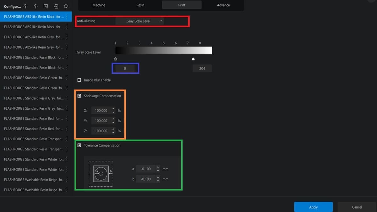
- Anti-aliasing (red): This reduces spatial aliasing. Simply put, it will make the surface of the 3D model smoother. The slicer reduces the whiteness of the pixels on the outer edge of each layer (which is originally completely white, and forms jagged edges), so that they form smooth transition curves. Options include “None”, “Gray Scale Level”, and “Anti-aliasing Level”.
- Anti-aliasing level is recommended for old slice file formats like “cbdlp”. In our case (a CBT file), a gray scale level is recommended. We opted for zero (blue), which implies more gradients on the edges, making them smoother.
- Shrinkage Compensation (orange): Because the mold cavity can’t be smaller than required, we’ll enable and set the shrinkage feature for the three axes (X, Y, Z) to 100% (for uniform compensation), to make up for for any shrinking.
- Tolerance Compensation (green): Because the mold cavity can’t be bigger or smaller than required (i.e. the molds swelling up), we’ll enable the tolerance compensation feature. The inner diameter compensation applies to closed inner contours, like holes or hollowing on each layer of the model. The outer diameter compensation applies to the outer contours. In our example, we’ll set “a” (the area within the contours of the cavity) as “-0.1 mm” and “b” (the external contour of the mold) as “-1 mm”.
Last but not least, click “Apply”.

Slicing & Exporting
Once the model is ready, it’s time to slice and export it for 3D printing.
- Click the “Slice” button. After creating the instructors for the printer, you’ll land on the preview UI.
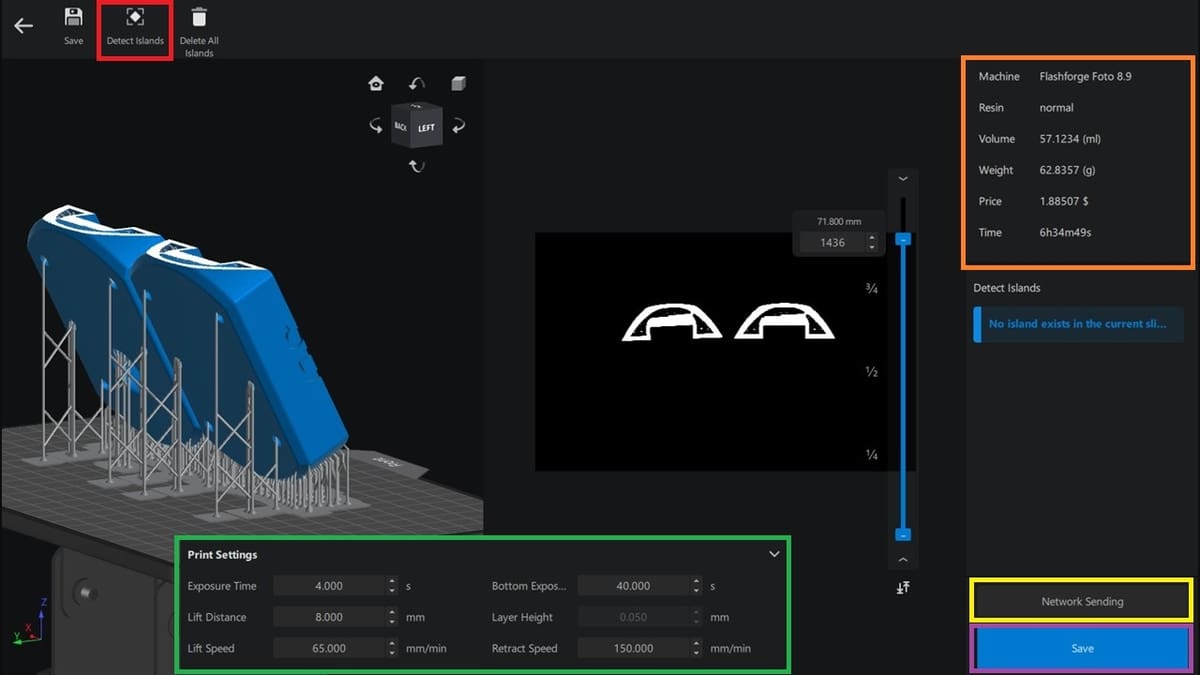
- Review the sliced model to ensure that supports are placed correctly and that there are no potential print issues. You can double-check that all the print settings are correct (green), and you’ll also see the weight and time of the print, among other details (orange).
- Should there be any islands in the print (i.e. parts that can’t be printed because they’re not connected to supports or to the model), the Detect Islands feature (red) can be applied to verify this and make any necessary corrections.
- With everything verified and looking good, the sliced file can be saved to a USB drive or local folder (purple), or if the 3D printer is connected through the network, it can simply be sent (yellow).
Tips & Tricks
While Chitubox has plenty to offer and it’s fairly straightforward to use, that doesn’t mean that there won’t be a few challenges along your resin 3D printing journey. Of course, there might also be issues with the 3D printing itself that don’t necessarily relate to the slicer, but which can be addressed by it. Let’s briefly discuss a few.
- Dimensional accuracy: As mentioned earlier under the advanced settings, the shrinkage and tolerance compensation feature can help ensure your prints come out according to size. However, when these features are still not giving the desired result, you might want to consider calibrating your printer if you consistently encounter size discrepancies.
- Delamination: If you notice that the layers of your cured print separate from one another (most often the bottom layer and the regular layer), you’re facing delamination. This can be caused by many factors and is almost always machine-specific. Confirm that the print orientation is appropriate, that the resin in the vat isn’t mixed (i.e. a mixture of used and new resin), and that the print hasn’t been halted for a long time before continuing (e.g. to add more resin in the vat). If none of these are an issue, from the settings in the slicer, increase the waiting time before a lift occurs and decrease the lift speed and retraction speed.
- Other failures: From first layers that don’t cure properly and lead to the model coming loose, to support failure, many additional issues might take place. For best results, it’s always recommended to look at the resin manufacturer’s suggested settings and ensuring that they reflect what’s been added by default to the slicer. Chitubox also includes quite a few troubleshooting tips depending on the problem.
License: The text of "Chitubox Tutorial: Hands-On Tutorial to Get Started" by All3DP is licensed under a Creative Commons Attribution 4.0 International License.