CNC Design – How to Design Parts for CNC

CNC machining is a common industrial process with specific design features that work best. Learn the ins and outs of CNC design as we break them down in this detailed guide.
The CNC Process, Explained
Computer numerical control (CNC) machining is a subtractive manufacturing method using a number of high-speed, precise machines to achieve desired structures. Basically, parts of a block of material are gradually stripped away using a variety of methods, including cutting, drilling, beveling, and slotting, among others.
As with all manufacturing processes, better results can be obtained by accommodating the specifics of CNC machining into the design stage. Following a brief review of the kinds of CNC machines, this article will go into detail on a number of design aspects.
Types of CNC Machines
Some of the common types of CNC machines include the following:
- Lathe: Commonly used to manufacture complex cylindrical shapes, for a lot of designs, the lathe is the first port of call due to the cost-effective nature of its operation. The material turns while the cutting tool remains stationary. Geometry creation relies on the movement and feed rates of the stationary tools as well as the rotational speed control of the material.
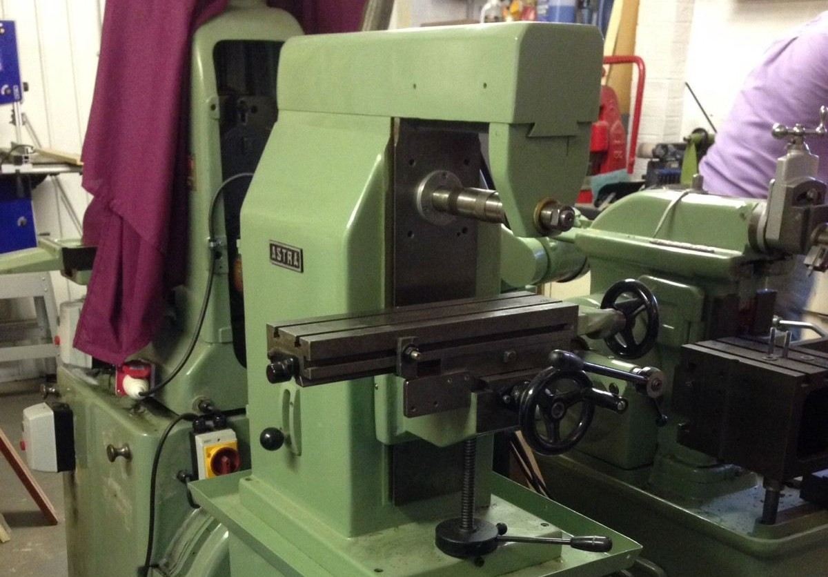
- Vertical milling machine: The spindle axis (and also the cutting tool) is aligned vertical to the machines’ bed. The difference compared to the lathe is that the cutting tool moves.
- Horizontal milling machine: Cutters are mounted on a horizontal spindle across the table. They are used when a lot of material needs to be removed by the cutters or there is less need for accuracy.
- Router: Similar to the vertical milling machine, cutting tools are aligned vertical to the machine’s bed, and the router moves while the part remains fixed. The main difference is the work-area-to-machine ratio, which is almost 1:1 for a router but closer to 1:3 for a mill.
For all the above machines, material is removed from a solid block of metal or plastic, with various high-speed cutting tools performing the different processes required. The majority of tools used for CNC processes have a cylindrical shank with a specific tip shape and a limited overall cutting length.
As the material is removed from the workpiece, the geometry of the tool is transferred onto the part. This means internal features of a CNC-machined part will always have corner radii, no matter how small the cutting tool selected for the process.
How It's Made: Materials
Material selection is critical for determining the cost of the part. Characteristics to be considered when selecting them for machining include hardness, rigidity, and chemical resistance, among other mechanical and aesthetic qualities.
Common metals for machining include the following:
- Steel: All steels are made up of iron and carbon. The amount of carbon and any additional alloys determine the properties of each steel grade. There are a vast number of different grades and types to suit many applications. Good machining grades include Stainless Steels 304 and 316 (offering formability, weldability, and corrosion resistance) as well as 4130 (provides enough strength, toughness, and fatigue resistance to be used in military and commercial aircraft parts).
- Aluminum: Aluminum is the world’s most abundant metal. Pure aluminum is soft, ductile, corrosion-resistant, and highly conductive. Aluminum can also be alloyed with other metals to enhance certain characteristics. Important grades for machining include 6082 (excellent corrosion resistance and strongest of the 6000-series alloys) and 6061 (good corrosion resistance, formability, and weldability).
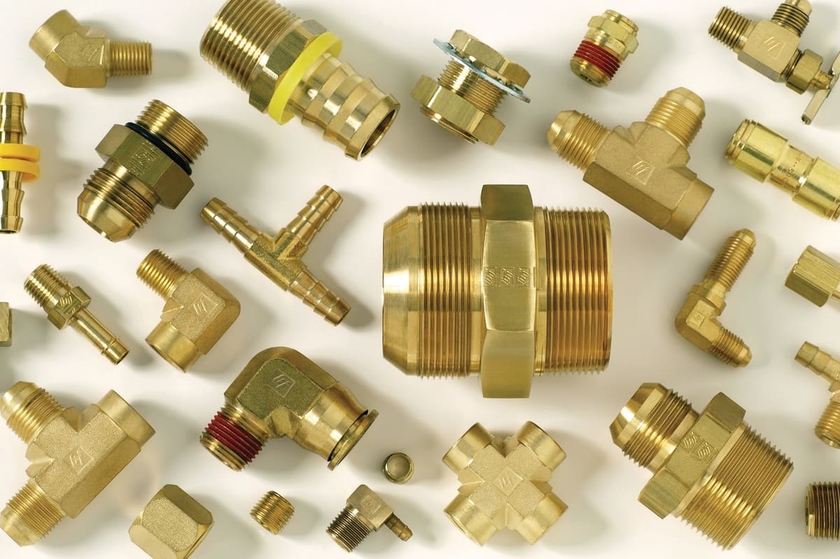
- Brass: Brass can provide high strength, high machinability, and corrosion resistance. These characteristics make it an ideal material for lower pressure hydraulic connectors and low-friction items such as locks and ammunition. It is also well used for decorative purposes due to its resemblance to gold.
- Copper: Excellent electrical conductivity makes copper grades the ideal product for electrical items such as busbars and motors, but is also used in radiators, roofing, and guttering due to its corrosion resistance. Machining copper is generally an easy process since copper is a good heat conductor that is easy to shape.
The range of plastics available for machining include:
- Nylon: Nylon is a synthetic thermoplastic linear polyamide that comes in a series of grades, similar to steel and aluminum. Key characteristics include good machinability, high compressive strength, and high friction resistance. It’s also a fairly economical option. It can be used in place of metal in some applications, providing a longer-lasting and lower maintenance solution.
- Delrin: A type of acetal copolymer, Delrin is a lightweight, low-friction, and wear-resistant plastic with similar properties to nylon but with better machinability and, most importantly, the strength and stiffness required to replace metal. Common applications include insulators, bearings, gears, and bushings.
- PTFE: More commonly known as Teflon, PTFE has excellent frictional resistance and is ideal for parts requiring durability and high impact strength. PTFE has a very low moisture absorption rate, making it ideal for wet environments, unlike other machined plastics such as nylon. Key applications include insulators, valve components, bearings, and spacers.
- PEEK: Polyether ether ketone (PEEK) is ideal for high-strength and high-stiffness applications. Additionally, having high resistance to heat and moisture cycles as well as chemicals, PEEK is ideal for pump components, medical implants, and aerospace components.
How Close is Close Enough: Tolerances & Fits
Tolerances define the acceptable range for any given dimension. If no overall tolerances are defined, most machine shops will use a standard tolerance of ±0.125 mm, but it is usually important to define your own standard as the application may require a tighter tolerance than this.
Fit can be referred to as the proper application of tolerances, and are either specified as shaft-basis or hole-basis fits. Fits can be split into three categories:
- Clearance fit: The hole is larger than the shaft, allowing both parts to either slide or rotate when assembled.
- Transitional fit: The hole is the same size or fractionally smaller than the shaft, requiring a small amount of force to assemble or disassemble.
- Interference fit: The hole is smaller than the shaft and a high force (or heat) is needed to assemble or disassemble.
Specific tolerances should only be used when the fit needs to be controlled for two or more mating parts. The following example takes in all three fits:
- Bearings-to-housing: Bearings being inserted into a housing where the outer race is held stationary and the inner race allows rotation need either an interference or transitional fit (depending on the material used in the housing).
- Shaft-to-bearings: Bearings are generally specified with either a transitional or minute clearance fit to allow the design of any shaft to be a whole number. It is important to check the bearing spec and the assembly as a whole within a CAD package to quickly flag any potential issues prior to manufacturing.
- Mounting the housing: Say the housing was mounted rigidly to a frame, the holes used to mate the two parts would need to meet a specific clearance.
But say the housing is one of three housings set up across a larger frame, with a long shaft (or axle) running through all of them, how do you control clearances of the mounting holes but also the concentricity of the bearings for the shaft?
This is where geometric dimensioning and tolerancing (GD&T) comes in, using a symbolic language to explicitly describe nominal geometry and the permissible variation. For our example above, you could control fit using either concentricity or position characteristics.
Although standard tolerancing generally suffices for part design, for more complex parts where features have bearing on each other, certain geometric characteristics used in GD&T (flatness, straightness, cylindricity, concentricity, etc.) are necessary. Make sure to avoid any unnecessary tight tolerancing as this may increase part cost by slowing machines down, requiring additional jigging, or using special measurement tools.
Drilling Down: Holes & Threads
Holes
- Drilling depths: Keep drilling depths low to avoid specialist tooling, and don’t specify flat-bottomed holes unless completely necessary
- Extended holes: For extended holes, the part can be drilled from both sides. It is important to recognize that there will be a mismatch where the two holes meet, though, and this can be remedied using jigging at an increase to part cost.
- Edge drilling: For edge drilling, ensure the entire diameter of drill is contained within the part. If any part of the diameter is outside, then the drill may break, surface finish will be poor, and the sharp edge created at the corner is likely to fold. If completely necessary, drill the part first and then mill material away to leave a partial hole.
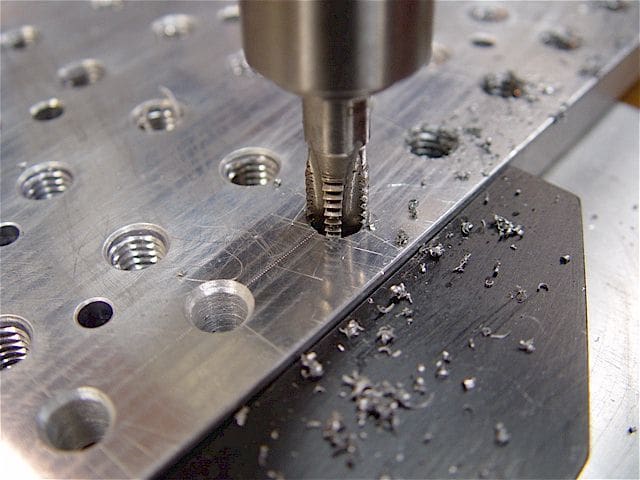
Threads
- Methods: There are three main methods for creating threads.
- Cut taps: Creates the female portion of the mating pair by removing material from the hole.
- Form taps: Creates thread by displacement of material within the hole.
- Thread mills: Inserted along the axis of the spindle using helical interpolation to create the thread.
- Hole types: For tapped holes, through-holes are ideal as this allows the tap to pass all the way through the part and guarantees an accurate thread is created. For blind holes, add a length over the threaded length that is 1.5 times the nominal diameter at the bottom of the hole.
- Thread size: Ensure the largest thread size possible is chosen due to ease of manufacturing. A smaller tap means there is a greater chance of breakages during production.
- Thread depth: Only thread the part to the necessary length, since deeper threads increase cost and off-the-shelf sizes keep costs down. Check with your chosen machine shop what threads they possess.
- Drawing details: Denote threads to be added to your quote and include an accurate 2D drawing detailing any threads to avoid confusion and ensure the parts you receive match the design.
Living on the Edge: Chamfers & Fillets
- Chamfer: Slope cut where two surfaces meet at a sharp edge, with the aim of easing assembly (for inserting bolts into holes) and also reducing risk of injury when handling sharp objects.
- Fillet: Rounding of an interior or exterior corner of a part, this feature is often a result of the cutter radius. It is important to keep any radius on the part greater than the cutter radius as this will lead to a more straightforward machining process.
- Deburring: Note that there is a difference between chamfering and deburring. The machinist will only break the edges of the part to deburr but will chamfer the material if a specific size is required. The edge on a chamfer should be kept at 45° unless it is vital that a different angle is needed.
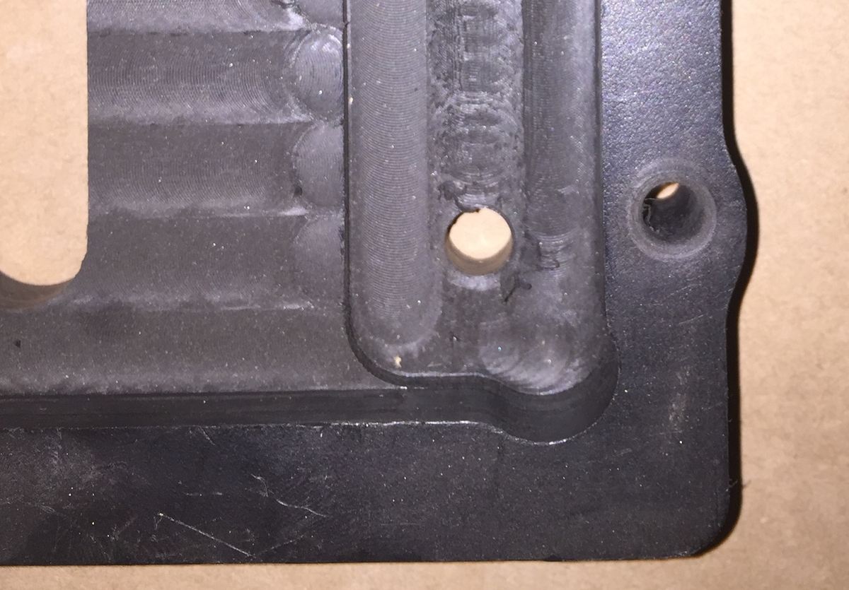
- Internal fillets: Internal fillets should be as large as possible to allow a large-diameter tool to be used, decreasing machining time. In general, the radius of the internal fillet should be greater than 1/3 of the depth of the cavity to avoid breaking the tool.
- Dog bone corners: If a square corner is required for a mating part, a dog bone corner can be used to remove the material surrounding the corner. The corner diameter should be as large as possible for ease of manufacture.
- Bottom edge fillets: When creating a radius on the floor of a pocket, it is easier to machine with a radius less than the radius on the walls. This allows the same tool to be used, creating a smooth flow through the corner.
Beneath the Surface: Undercuts
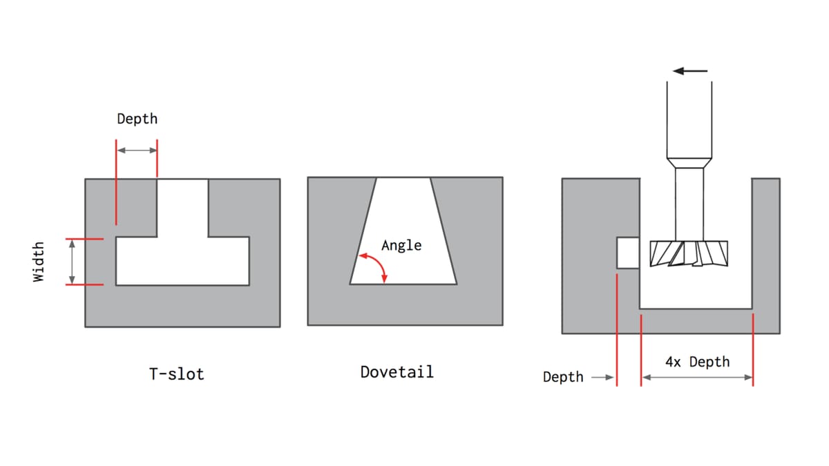
Undercuts are features that cannot be machined using standard cutting tools, as some of their surfaces are not accessible directly from above. There are two main types of undercut features:
- T-slot: Cutting tools comprise of a horizontal cutting blade attached to a vertical shaft, and to limit cost increase in these scenarios, use whole millimeter increments or standard inch fractions for tool width.
- Dovetail: Cutting tools use the angle as the defining feature size, with standard tools being 45° or 60° (tools up to 120° at 10° increments are also available).
When machining, it is best to avoid undercuts as they are difficult to machine and require specialist tooling or multiple setups. If completely necessary, keep the undercut amount as small as possible.
For undercuts on internal walls, add enough clearance for the tool. Add space equal to a minimum of four times the depth of the undercut between a machined wall and any other internal wall.
Surface Finishes
The most common finishes for CNC-machined parts are as follows:
- Milled finish: Due to the nature of CNC machining, some tool marks will be visible on the parts’ surface. Surface quality is measured by the average surface roughness, which is defined as the average deviation of the machined profile from the ideal theoretical surface. This finish gives the tightest dimensional tolerance and there are no additional costs to this finish, but the visible tool marks from milling will affect the part aesthetically.
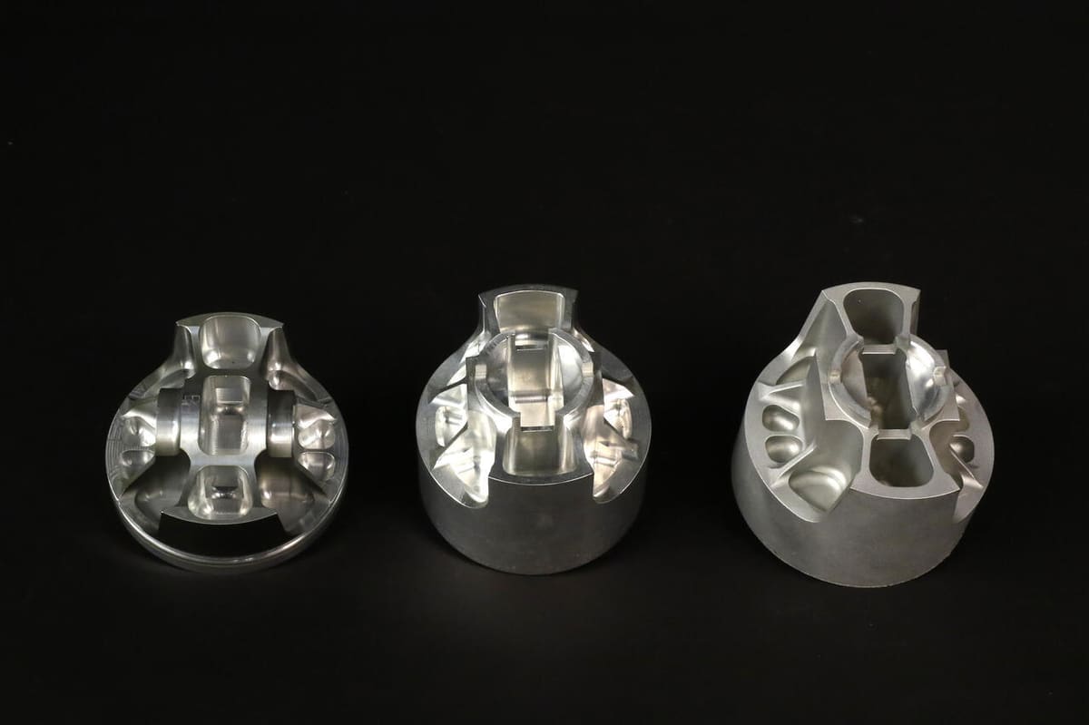
- Bead blasting: A uniform matte or satin surface finish is added by bombarding the part with small glass beads using a pressurized air gun to remove some material and smooth the exposed surfaces of the part. Critical surfaces and features can be masked to avoid any undesirable dimensional changes. The manual nature of this process means that the finish quality is heavily dependent on the skill of the operator but can yield a variety of different finishes depending on the size of glass beads used (from coarse to very fine, in a similar vein to sandpaper grades. Bead blasting can also help to relieve some of the stress risers left behind from machining, which can come in handy on mechanically-strained components such as pistons where any concentrated stress greater than material strength in a given area has the potential to originate a fatigue crack.
- Anodizing: A process by which an oxide film is formed on either an aluminum or titanium part in a chemical solution known as an electrolyte. There are different types:
- Type I is a Chromic Acid anodize used in aerospace and other precision machined components. It’s ideal for welded assemblies. Black dye is commonly used in this process, since other colors are not as practical. This finish can also be used as a primer for a higher quality powder coating finish.
- Type II involves a diluted sulfuric acid and is known as a “standard” or “decorative” anodizing, producing parts with a smooth surface with good corrosion and limited wear resistance, but still with good application to parts requiring tight tolerances.
- Type III also uses diluted sulfuric acid but is a “hard coat” producing thick ceramic coatings with very high corrosion and wear resistance and is primarily used on sliding parts and hinge mechanisms as well as other mechanically stressed parts such as valves and pistons.
- Powder coating: Adding a thin layer of protective “paint” (which is a dry powder rather than a liquid spray) on the part’s surface, providing a strong and wear-resistant finish compatible with all types of metal. Parts which are powder-coated have a higher impact resistance than anodized parts since multiple layers of powder coating can be applied with a wide range of colors. However, this does result in less dimensional control than in anodizing. Also, due to the nature of the application, it’s not easy to coat internal features and surfaces.
- Electroplating: One or more layers of metal are applied to the part by passing a positively-charged electrical current through a solution with dissolved metal ions (anode) and a negatively-charged electrical current through the component (cathode). Customized properties can be added due to the use of single metals such as tin, lead, and zinc, among more aesthetic metals (gold and silver). This process is commonly used in finishing medical diagnostic instruments, electronics, and optics.
Other specialist finishes such as dry lubricants (reduces friction) and other performance-enhancing finishes are available, so it is important you do due diligence for your application.
Things to Avoid
- Thin walls: Hard to machine and easy to fracture, thin wall machining requires multiple passes at low cutting depths, ramping up the costs. Thin features are very prone to vibrations as well, so machining an accurate thin wall is very challenging and time consuming.
- Deep cavities: Cavity depth should be kept under four times the tool diameter in order to reduce the machining difficulties and potential for tool breakages.
- Small features: Micro holes are one such example (under 2.5 mm in diameter), increasing both machining difficulty and time, affecting cost negatively in the process.
- Embossed text: Due to the large amount of material that needs to be removed in this process, it is better instead to use engraved text. Using a sans serif font with a minimum size of 20 points is also recommended to avoid small features within the engraved text.
- Specific tolerances on non-critical features: The greater the accuracy required for machined parts, the higher the cost of the finished part due to increased machine time and labor. Specific tolerances should be defined sparingly and only when it is not acceptable to use the standard tolerance on the technical drawing.
Tips & Tricks
- Talk to your machinist: Find out about tool/machine capabilities & limitations before you design to produce the best possible parts. Also, find out about their off-the-shelf stock sizes to reduce cost and machining time further.
- Look for common parts online: Having spacers machined that could be obtained off-the-shelf is cost ineffective and time consuming for both designer and manufacturer.
- Submit a technical drawing: When your design contains threads, tolerances, or a specific surface finish, this is a good idea.
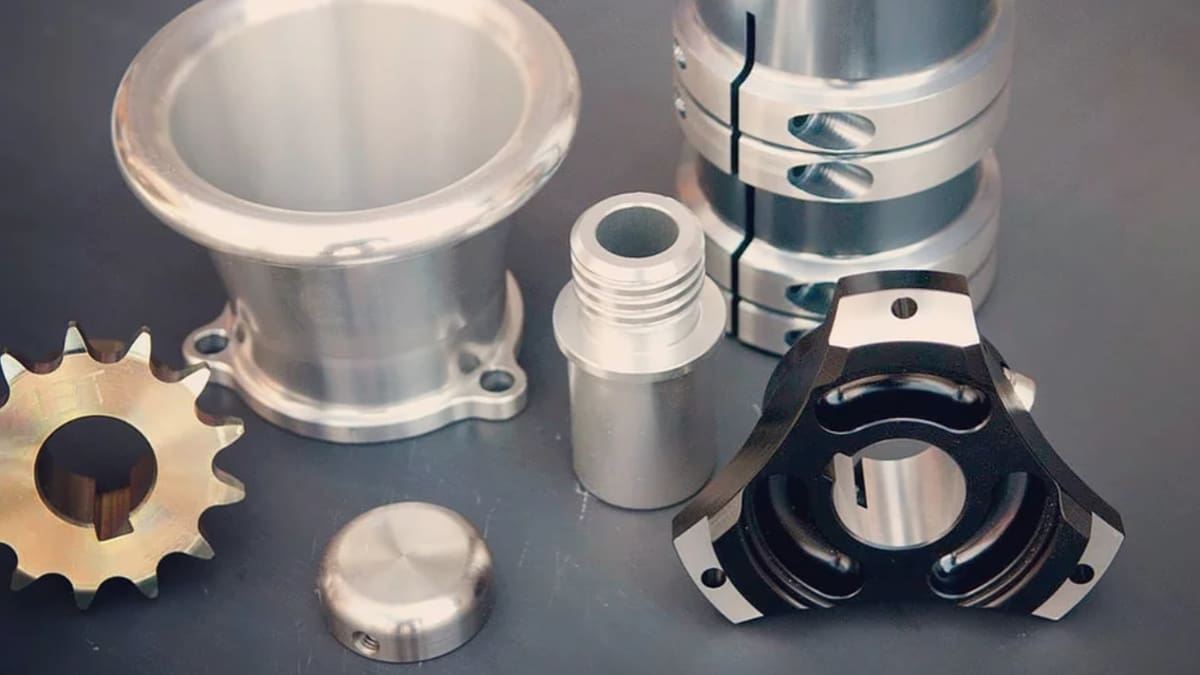
Feature image source: JC Engineering (Precision) Ltd.