
DIY CNC Router: Which Parts Do You Need to Build Your Own?

DIY CNC routers have a lot to offer. Find out more about CNC router parts and get some guidance to join the fun.
When it comes to cutting wood or milling metal, CNC machines offer a level of accuracy that’s hard to achieve by hand. For makers, this has always been an attractive proposition, as the creation of carvings, engravings, and complex cuts is done quickly and automatically.
A professional CNC machine may be out of reach for most, if not already in terms of money and operational know-how, most certainly in terms of space for the average workshop or garage. That’s where a DIY machine comes in. But how to make the right decision on which plan to follow or even what materials or parts to use?
A DIY CNC machine is a unique and individual solution, but the options can be many and confusing. If you’re considering building your own CNC machine but aren’t sure where to start, this article has you covered. We’ll discuss each main assembly within a CNC, what it is, what it does, and what it’s desirable traits are.
Our aim is to give you a good idea of what parts you will need to DIY your CNC machine. With that in mind, we should start with what type of machine you’re thinking of building.
Which Machine for Which Application?
It may seem obvious, but different machines are dissimilar for a reason. For example, cars and trucks both drive on the road, but they differ in their construction. Similarly, CNC machines for varying applications are very different.
Depending on your use, you may want a huge flat bed to cut out large plywood profiles, or you might prefer a small but tall work area for milling small, precise parts out of aluminum – or you may need a tank because you’re planning on making a waterjet. You may need ropes instead of other extrusions because you’re building a Maslow-style suspension router for art projects. There’s any number of other avenues that your build could take. Here are some of the common categorizations:
- CNC profile cutter: This includes plasma cutters, EDM machines, waterjets, and lasers. The machine is really 2.5-axis rather than 3-axis, as it can normally only cut all the way through the material. Although a partial depth cut or engraving is possible, it’s usually less accurate in the Z-axis because they don’t have a Z-axis per se, other than for focusing a beam or jet.
- CNC router: This is a simple 3-axis machine designed to cut one face of the work only. Most engravers and hobbyist machines (like 3018s and Mostly Printed CNCs ) fall into this category. They usually have a rotary tool as its cutter, but could be fitted with other tools as well.
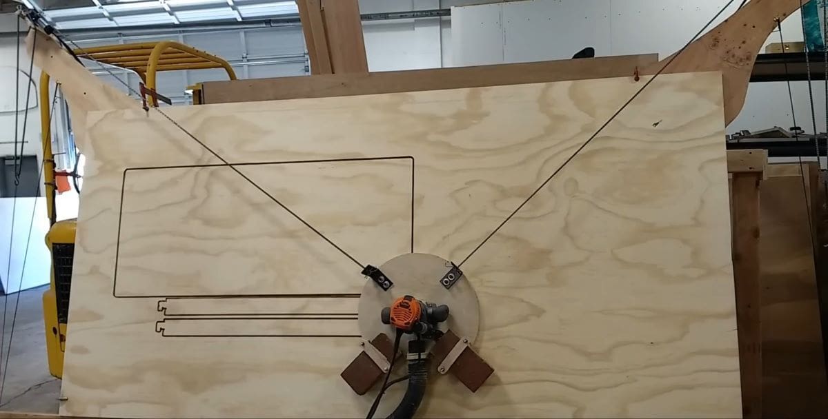
- Maslow CNC router: This machine trades rigid ways and guides for a suspension system and can be used for extremely large projects, such as cutting out panels for boat building or carving out huge signs.
- CNC milling machine: A 3- or more-axis machine that can be used to make complex 3D geometries. If they’re 3-axis, they’re similar to CNC routers, although normally the work will be moved in a milling machine and the tool is moved in a router. 4- and 5-axis milling machines can create extremely complex geometries with a very high level of accuracy.
Building a CNC machine isn’t a quick or easy undertaking. Therefore, it’s wise to honestly answer some questions about the use of the machine, because wasting time and material is frustrating, expensive, and wholly unnecessary.
Here are some of the questions to ask:
Where’s the machine going to be placed?
- How much space is available? This must include space for a protective noise cover, dust extraction, and possibly a PC with monitor and accessories.
- Is the machine fixed or does it need to be mobile?
The answers to the above will set out the very basic parameters. One can’t have a full-sheet-capable CNC router if there isn’t enough space for it. Think of neighbors regarding noise and think of access to the area around the machine for repair and service.
What are the expectations for the machine?
- Which materials are to be machined? The harder the material, the higher the requirements on all parts of the machine. Most DIY machines are suitable for wood and aluminum, but not steel.
- What level of accuracy is needed? For furniture making, a lower level of accuracy is needed than for making engine parts. Most DIY machines can achieve 0.01-mm accuracy and aren’t suitable for much more than furniture making and general woodworking. The larger the machine, the harder it is to achieve good accuracy because it depends on rigidity, as well as on an accurate build and as little play as possible in all parts.
- Is cutting of special materials, such as carbon fiber, foreseen? If so, a water bath may be needed to catch the hazardous dust, as well as to cool the material.
- Is the machine to be multi-purpose? For example, is it meant to serve as a 3D printer, vinyl cutter, laser cutter, or plasma cutter? It’s important to be realistic here because high precision sets high demands, which in turn imposes cost barriers. Multi-purpose requirements usually mean compromises in some aspects. A taller CNC machine is more likely to be less stiff and therefore less accurate, but 3D printing requires a sensible build height to do a little more than flat pieces only. Different build surfaces are required for different purposes: A metal grid’s needed for laser and plasma cutting, while a magnetic PEI surface is warranted for 3D printing (to name just two).
There’s only so much a light DIY CNC machine can do. High precision isn’t needed if the goal is to make toys and puzzles. For higher demands, it’s often more sensible to consider outsourcing the manufacture of parts via Craftcloud for both 3D printing and CNC machining.
What’s the skillset and capacity of the budding CNC machine builder?
- Low: The maker can follow instructions, do simple adjustments, but doesn’t have access to tools or the ability to make custom cuts or create parts by hand and isn’t confident in sourcing materials.
- Medium: The maker can follow plans, create some parts, and source materials based on provided specifications.
- High: The maker has high skills in designing and building parts and machines with or without plans and instructions.
For the Low category, ready-made kits are the way to go. They will cost a little extra, but it’s a way of avoiding some disappointment. If flat-pack furniture poses a challenge, however, think again and maybe purchase a wholly ready-made machine. The Maslow CNC router kit might be worth considering.
For the Medium category, a raft of possibilities opens up, from kits to plans, as long as the maker doesn’t venture too far from the plans in their project. These offer a level of flexibility, as the maker is able to adjust certain aspects to the hardware that’s available. Access to certain tools and skills or preferences will determine what’s possible.
For the High category, the sky’s the limit. Read up and go ahead – build a dream machine!

Parts/Components Needed
CNC machines have some things in common, but these may look wildly different and be called something different in each application. For example, on a traditional milling machine, the part we term “gantry” in this article is actually called a “turret”.
In short, you’ll need something from each category in this article. Depending on your build, you may need other things as well – or some parts will serve double duty. For example, the frame might form part of your transmission or (in the case of the Maslow) the workpiece might double as the bed and frame.
We’ve grouped the major subassemblies by function and stuck with the names most likely to be used on a DIY machine. You’ll need to do further research on the machine you intend to build, but we hope you find this a useful starting point.
Frame
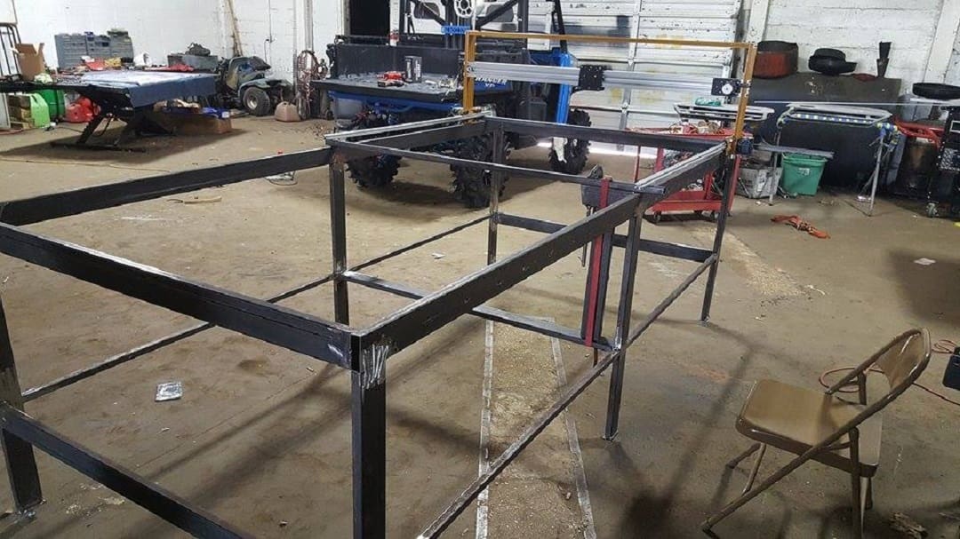
The frame is the what defines your machine and supports all the other parts, and it usually provides a solid object for the transmission to push against (more on transmissions later). If you’re looking at a CNC machine that isn’t enclosed, it’s likely you’re mostly seeing the frame. It provides mounting points for all the various components.
What Do We Need a Frame to Be?
In order to do its job effectively, a CNC frame must be rigid and square.
By square we don’t mean square in shape, we mean that the angles between each element of the frame must be precisely known (sometimes down to arcseconds). The shape of the frame sets the axes of the machine so, to make everyone’s life simpler, these angles are usually specified at 90 degrees – hence why we use the term “square”. The angles between the axes are known by the software and often can’t be changed (another reason why 90 degrees is often used).
Rigidity comes down to the angles between the axes. If a member of the frame flexes by a few millimeters in the center, the angle where it attaches is no longer the same as what was defined in the software. So, the piece being machined may be scrapped (unless it has very loose tolerances), or the cutting bit may be broken by shear forces.
What Should the Frame Be Made of?

Frames can be made from anything that’s both sufficiently stiff and strong enough to counter the cutting forces. People have made frames out of plastic and wood. These machines tend to struggle with accuracy when cutting harder materials, but might be enough for light engraving work (for example) on soft metals.
Cast steel is the gold standard for heavy duty machines, but it’s expensive, heavy, and must be manufactured in a foundry to shape – so it’s not very good (or even possible) for DIY builds.
Welded steel is the next best thing, and if you can weld and do it squarely, then this might be the best option with the greatest flexibility. Bolted steel is also worth considering; it’s slightly less flexible than welded steel if you need to make large changes, but it’s much easier to adjust and to get everything square and true.
Extruded T- or V-slot aluminum profiles or raw profiles (such as angles and box sections) are an excellent choice. They’re more expensive than steel but much easier to work with, and they won’t rust. You can use readily available tools and, in the case of T-slots and V-slots, you’ll have amazing levels of flexibility and adjustment. The trade-off is that they’re less rigid than raw profiles (due to the friction fasteners) and much more expensive.
The best option is usually a mix of materials with each providing their best properties in the area they’re used. For example, in the MPCNC, a steel and plastic frame is used: a steel tube for rigid long members and 3D printed brackets for ease of home manufacture and adjustability.
Bed
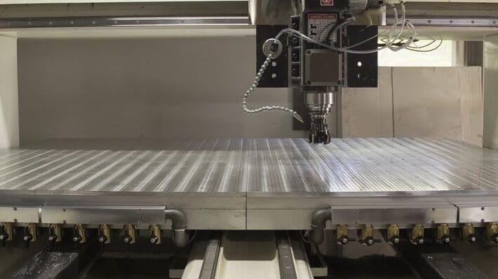
You sleep in it…That’s not the type of bed we’re talking about. The bed we’re talking about is the part of your CNC that supports and holds the workpiece in place against cutting forces (and sometimes also gravity and lots and lots of coolant). It often also has some way of ensuring that you can cut right through a piece without damaging it.
What Do We Need a Bed to Do?
As mentioned, a bed needs to hold a workpiece against cutting forces. It may also need to be mobile. In a traditional knee milling machine like a Bridgeport, the bed (and therefore the workpiece clamped to it) moves relative to the tool. The bed needs to provide a mechanism for clamping the workpiece down and may also need to allow space below the part for the cutting tool to protrude through. This can be achieved using a spoil board or a raised work-holding system.
A spoil board protects the bed from damage if there’s a chance of cutting through the workpiece when machining. It may also be necessary at times to ensure a clean edge finish. Spoil boards are meant to be consumable and need replacing after a while. They can last a long time, though, and may be able to be re-flattened repeatedly depending on the machine.
The bed or clamping system should also provide the means to ensure that any work is square to the machine. This isn’t normally an issue for the first cuts from stock material, or if it’s a wide tolerance part like a sign where a few hundredths of a degree will be invisible to the naked eye. But if you’re making mechanical parts that need to fit together, or aero/hydrodynamic parts like foils or propellers, this can be critical. Of course, in very high precision parts we use the tool to measure and square our stock, but that technology can be harder to fit to a DIY machine.
The easiest way to ensure that your parts are well aligned is to ensure that your bed is flat, and in most DIY machines, that can be achieved using the machine itself to skim away part of the spoil board.
What Should the Bed Be Made of?

Professional beds for metal CNC are cast steel or cast iron with T-tracks ground into them. This allows the use of very rigid clamps that bolt the workpiece down. On this type of bed, if there’s a chance of cutting through the material, spacers are used to hold the work off the bed to allow clearance for the tool.
Other types of bed include medium density fiberboard (MDF), aluminum T-track, metal grids, or arrays of pipes or plates, all of which provide different capabilities.
MDF beds are seen on some hobbyist machines or on industrial machines that incorporate a vacuum work holding arrangement. Frequently, MDF beds double as the spoil board for the machine, and it’s usually beneficial if you use an aluminum T-slot bed to install an MDF spoil board on it. You can even use your machine to make and flatten its own spoil board.
Aluminum T-track beds are most often seen on hobby CNC machines like SainSmart’s Genmitsu or FoxAlien machines. These T-tracks often incorporate MDF bump pads that could double as a spoil board, but can be hard to replace.
The grids and pipes types of bed are normally used for laser, plasma, or waterjet cutters, and are designed so that the cutting energy can pass through without also shredding the bed. They’re normally quite deep and include fume extraction in the case of lasers or plasma, and provide a tank to collect the water and garnet for recirculation in the case of a waterjet.
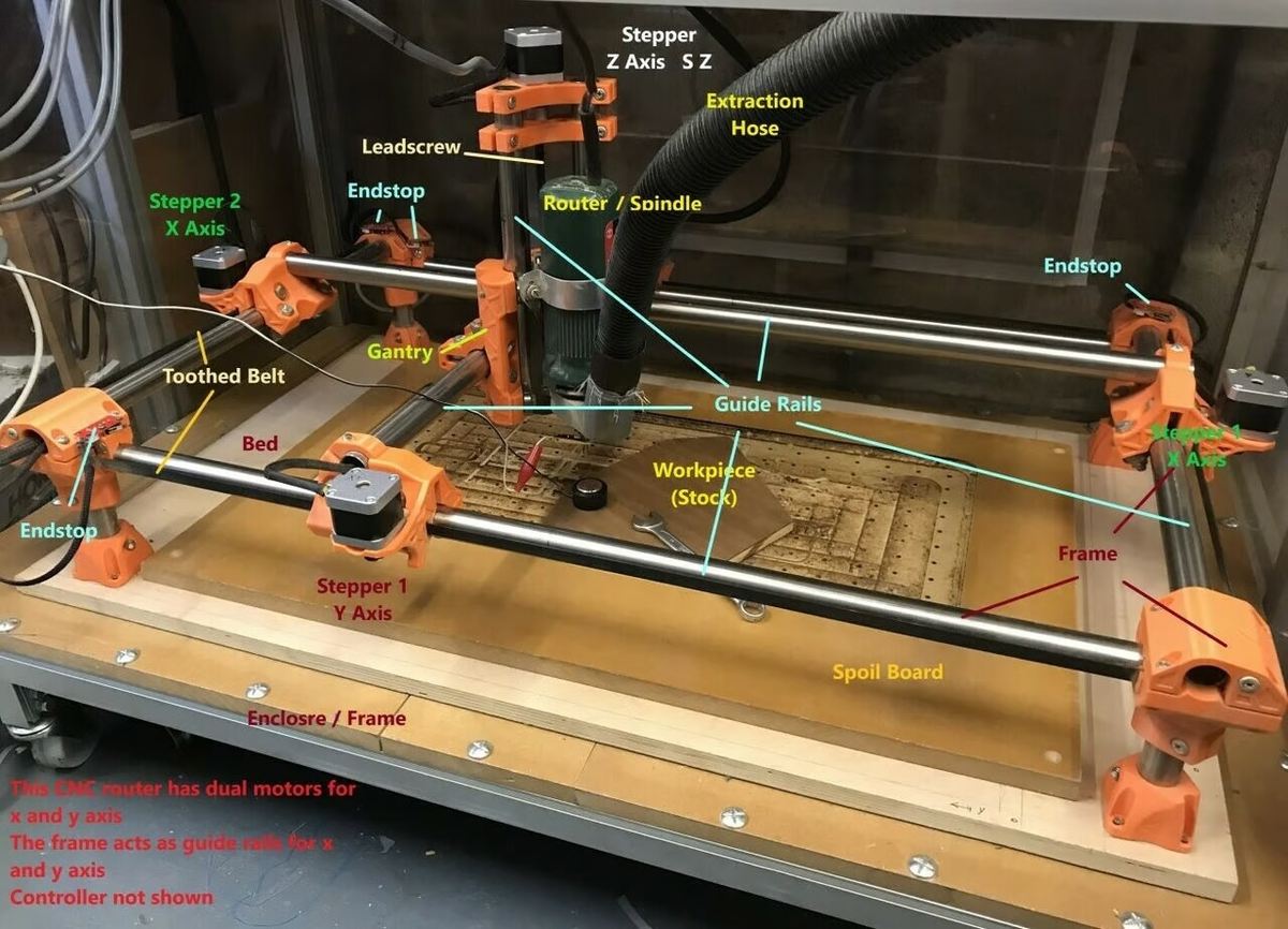
Gantry

The gantry is the part of the machine that supports the toolhead over the bed (and the workpiece). It may be mobile or fixed, and may contain features such as the ability to cant for angled cuts. An example of a fixed gantry would be on a knee mill. For DIY and hobbyist CNC, it’s fairly normal that the gantry moves in the Y-axis and has a carriage to move the toolhead in the X-axis. In some cases, such as the MPCNC, the gantry moves in both X- and Y-axes.
What Are the Gantry’s Desirable Qualities?
The gantry should be rigid in order to ensure that the cutting tool is positioned as precisely as possible. If the gantry is moveable, it should also be fairly lightweight to reduce the power needed by the motion system to move it. It will also need a means of powering the toolhead, be this cable trays, an umbilical, or internally routed power systems. Lastly, if the gantry is moveable, it must contain the means to transfer motion to the toolhead, such as a lead screw, belt and pulley system, or some other mechanism.
What Should a Gantry Be Made of?
The gantry is usually made from the same materials as the main frame of the machine, but with added rails, slides, or rollers to enable any required motion. It may also have more solid areas, such as side panels instead of extrusions, to increase rigidity.
Toolhead
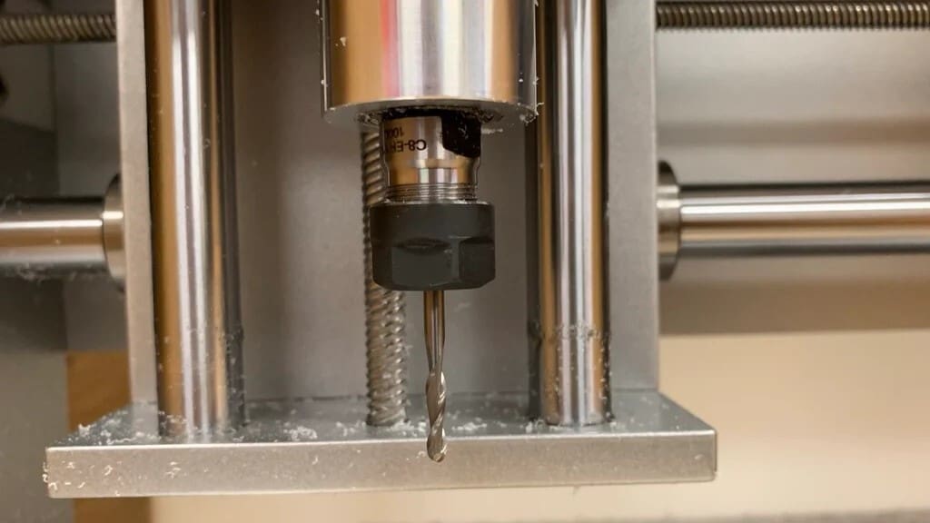
The toolhead is the business end of the machine. It’s what holds the part that will do the cutting and often provides power to the tool itself, usually in the form of rotary motion (with some key exceptions).
What Does a Toolhead Need to Work?
To do it’s job, the toolhead will need a mechanism to perform the kind of work that you want on the workpiece. So, if we look at a plasma cutter, the toolhead will need a plasma torch; for a water jet, it will need a nozzle. For most DIY CNC systems, it will need a spindle and chuck. There are many spindle options, ranging from conventional handheld routers to dedicated CNC spindles, the latter being already prepared for signals from a microcontroller. Cutting bits like end mills are turned by the spindle and cut away parts of the stock to reveal the finished part.
Many toolheads will also include some method of removing swarth and dust from the workpiece. This could be as simple as a bracket to hold the hose of a vacuum, or as complex as a flood coolant system that washes dust and swarth into a catchment.
What Are the Options?
There’s a bit to unpack here depending on what you want from your machine. If you want to cut sheets of steel for welding projects, you’ll likely be looking at a plasma cutter. If you’re looking at anything with wood, you’ll probably want a router. Each toolhead has it’s own number of strengths and weaknesses.
Due to cost and complexity, it might be best to stick to either a rotary toolhead, such as a router or spindle, or if you’re familiar with metal work and the safety requirements, a plasma cutter.
Waterjets are among the most flexible and capable tools on the market, but require tanks and garnet injectors and high pressure pumps. Lasers can do many of the jobs that a water jet can do (and some that it can’t), but to get that capability you need a fiber laser. And even then you have be careful because a reflective material will send high power laser energy into places you really don’t want it. Trust us, the safety door melts faster than you’d think. Electrical discharge machining (EDM) can bring insane precision, but involves discharging an extremely high power electrical supply into a water bath, which has some significant safety implications.
Stepper Motors
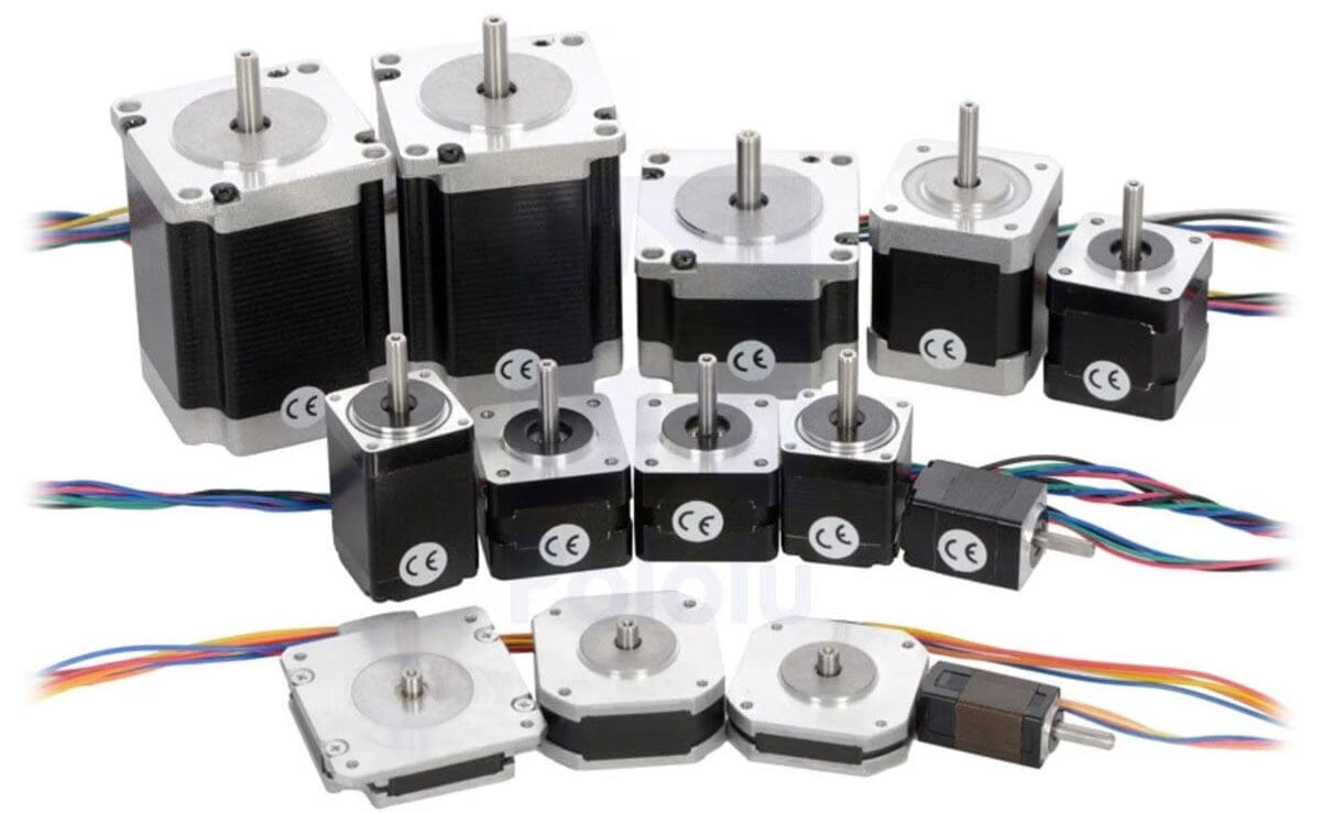
Put simply, stepper motors provide the motive force to move the toolhead relative to the workpiece. They normally do this by applying torque to the transmission system (linear motors exist, but are rare). Large machines may require larger stepper motors or even two per axis.
What Makes a Good Stepper Motor?
A good stepper motor produces ample torque at high speed and is controllable to a high accuracy. All motors made by humans are a compromise though, and you’ll need to look at the best system for your application. You’ll need to consider the size and weight of the motor, particularly if it’s going on a moving gantry, and ensure that the shaft output is in line with your transmission system.
What Are the Options?
Most DIY routers will work very well with some NEMA series stepper motors. These rotate in known increments and can just be pulsed the correct number of times to achieve the desired position. They’re available in a variety of sizes, and there are many, many off-the-shelf transmission components to suit the various sizes. You will also need a set of drivers (a piece of hardware) to “translate” the commands from your control electronics to the pulses the motor needs to move. These will need to be sized correctly to the motors they drive.
If you need greater precision or repeatability, you may consider a servo motor, which measures the actual angular position of the motor shaft and will drive that motor to reach the commanded position. The control electronics for these are usually self-contained, but the programming to allow the control electronics to speak with a servo is a little more complex to set up.
Transmission Systems

The transmission system turns the rotary motion of the motors into linear motion of the tool relative to the workpiece. It can achieve this by moving the tool or the workpiece or, in many cases, both.
The transmission system also include the system that restrains movement of any part to the desired axes. So, guide rails would be considered part of the transmission system. If the frame or gantry forms part of your transmission system (for example if you’re using V-groove rollers or the frame is made of tubular guides), then it must meet the criteria for both systems.
What Makes a Good Transmission System?
A good transmission system will have no distortion from cutting forces, no discernible backlash, and be just as or more accurate than your motors. Achieving low distortion means that the system is mechanically robust enough that it won’t change shape during cutting (even if you ram the toolhead into the workpiece). Low backlash ensures that a 50-mm command means a 50-mm movement even when changing direction. High accuracy transmissions have lots of little teeth (or work on friction) to allow a smoother power transfer.
What Are the Options?
This is going to depend on what you’re going to do with your machine. If you’re going to make extremely precise parts, ball screws are really the only answer. If you’re okay with slightly less accuracy (but still finer than you can see), then lead screws and timing belts are a good option. If you need raw power and speed, then chain drives might be the way to go – but beware as they are extremely difficult to make accurate.
Control Electronics
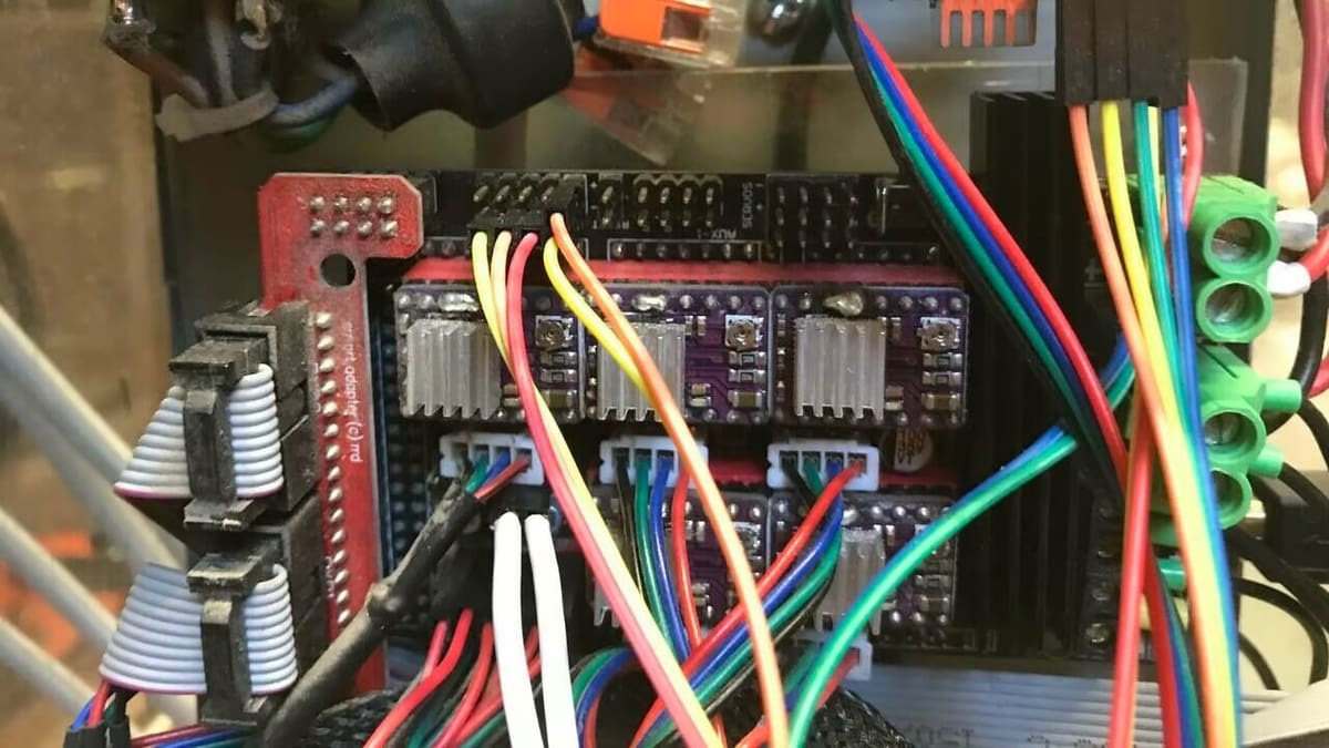
The microcontroller board controls the stepper motors and spindle, monitors end-stop states, and translates G-code input into machine movements. Boards range from the humble Arduino Uno to Esp32-based microcontrollers and offer something for every need. They all work, but not necessarily with every firmware and software combination.
What Does Your Control Electronics Need?
In a nutshell, the control electronics is going to be specific to your setup. This is where experience really comes into play. If you’ve built a few DIY kits of different types or already used several machines, you’ll have a feel for what’s needed to make your machine go.
This may need to be coupled with dedicated electronics to control high power stepper motors, special variable frequency drives for the spindle, a servo control system for super precise operation, and maybe even power electronics to correctly spool up a waterjet pump or gas control valves to control a plasma torch.
You will also need accessories like end-stops and Z probes. Most of these are optional on a CNC machine and many hobbyist grade machines you can purchase have no accessories. They do make life a bit easier though, as performing scratch tests to find the perfect top of the stock, and double and triple checking G-code to ensure no collisions, can be extremely time consuming – not to mention frustrating and expensive when you get it wrong!
What Are the Options?
For most new CNC machinists, even the most simple of boards, like the GRBL based on the 8-bit Arduino Uno, should be sufficient, but it all boils down to personal choice. More modern boards based on more powerful processors provide a smoother and often quieter experience in terms of stepper motor noise, but it’s not something to unduly worry about. Just keep in mind that larger stepper motors with higher current draw might push the more basic boards to their limits.
Physically building a CNC machine is one thing, controlling it is another. In order to get from a CAD design to a machined piece, there are a number of steps to follow.
Unlike 3D printing, CNC routing or milling is a subtractive method. A 3D printing slicer would be of no use here. To generate the machine toolpaths in G-code or another acceptable format, we require a program that can generate toolpaths in relation to a given stock material, tool specification, cutting depth, and cutting speed. Such a program is typically referred to as the “software”. Meanwhile, while technically a type of software, what’s referred to as “firmware” is what lives on the microcontroller board.
What Software Do I Need?
In order to drive your CNC machine, you’ll need two and a half pieces of software…We call the third piece “a half” because it’s the firmware living in your machine and you won’t interact with it for the most part. The other two pieces of software are a toolpath generator and a G-code sender.
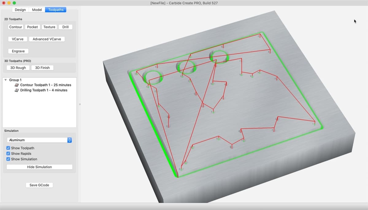
The toolpath generator is what you would think of as your slicer for your 3D printer, and the G-code sender is analogous to the front end of Klipper. Common toolpath generators are Easel, V-Carve, Carbide Create, and Fusion.
The G-code sender is the part of the machine you’ll interact with the most when using your CNC. It has controls for the machine and lets you run, pause, simulate, and often edit G-code, or create simple toolpaths for when breaking out the design software is just too much, for example to make a simple circular cut-out.
What Are the Options?
Whether software or firmware, there are plenty of options available for DIY CNC machinists, including both paid and free offerings. The latter includes open-source firmware for the microcontroller board and free software to create the required inputs. The choice comes down to personal preference, so it’s recommended to explore these options carefully because, for example, not every microcontroller board works with all firmware. For those coming from a 3D printing background, it will feel familiar to tinker with firmware upgrades.
There are, of course, other options, from being able to move all axes using an attached game controller to having a professional machine setup with a touch- or mouse-controlled graphical user interface (GUI). Some require an attached PC, while others don’t. Then there’s the issue of upgradability to more than 3-axis control in the future. Not every package offers that ability.
Our advice is this: Keep it simple – at least in the beginning. The beauty of DIY builds is that one can more simply upgrade in the future.
With the above in mind, let’s introduce some of the most popular programs in the DIY CNC world. This list is by no means definitive and further suggestions are always welcome.
Marlin

Marlin firmware is popular among 3D printers, and it’s also capable of controlling a CNC router. A wide range of microcontroller boards support Marlin, and there’s plenty of community support. It accepts G-code, which can be generated with free (for non-commercial use) software such as Fusion or FreeCad. It plays together with Estlcam software (which we’ll look at below) and Repetier host as G-code senders.
Both are optional and require a USB connection to a PC, but Marlin also accepts SD card input and can therefore work as a standalone solution with a minimal setup, involving just a graphic controller attached to the microcontroller board. For anyone coming from a 3D printing background, the attraction lies in the familiarity of dealing with Marlin.
GRBL
GRBL is the other popular choice, running on an Arduino Uno. It connects via USB to a computer with a keyboard and monitor to feed G-code to the microcontroller, as well as to control the machine. As with Marlin, support abounds because it’s been a longstanding program of choice for DIY CNC routing. The GUI is dependent on which program is used to send the G-code to GRBL. For example, CNC.js and GRBL plotter have nice user interfaces (UIs) and offer an intuitive way to operate the machine
Estlcam
Estlcam is another popular program that requires a permanent PC connection. It has a nice UI and good documentation, with the integration of a game controller to move the gantry, subject to using the Estlcam firmware. Estlcam can also work solely as a G-code generator for 2D and 3D models, and it works with many boards and different firmware setups. It is, however, only available on Windows. Estlcam comes with an unlimited trial, but its low price ($30-$60) makes it sensible to purchase the full version.
FluidCNC
FluidCNC offers an interesting port of GRBL to the much more powerful Esp32. The project is actively developed, with features like over-the-air (OTA) updates, on-chip storage for several configuration files, and online operation via phone or tablet making for a really interesting experience. It may not be advised for beginners unless they’re comfortable with configuring an Esp32-based controller.
LinuxCNC & Mach3
There are other options that are either complex like LinuxCNC or costly like Mach3. Both offer fairly sophisticated control over a CNC machine, including more than three axes, but their complexity or cost might make them unwise choices for beginners. These options also require a computer with a parallel port, which is rare today. For readers who are into antiques or who remember the clunky large connectors for printers, yes, that’s what’s needed.
Further Reading

Phew, that’s a huge amount of information right?
Having a general idea of (mostly) everything that’s expected, you might already know if building your own CNC router or machine is something you’re interested in. We suggest taking your time and going through the questions under “Which Machine for Which Application?” to help you narrow the scope of your project. If you can be strict with your requirements now, the whole machine will come together a lot smoother.
There are also plenty of books out there on how to build your own CNC machine. While these may not have the most up to date new release parts, they are an extremely handy reference, particularly mid-build when you may not have the spare hands to browse the web!
As mentioned, an excellent option is to start with someone else’s design or a DIY Kit – there are a lot out there to choose from. Another place to get inspiration is the OpenBuilds forums, where people post their projects.

License: The text of "DIY CNC Router: Which Parts Do You Need to Build Your Own?" by All3DP is licensed under a Creative Commons Attribution 4.0 International License.