Draftsight Tutorial: 4 Easy Steps for Beginners

Draftsight offers professional CAD tools at a fraction of the cost of other brands. Get started today with our Draftsight tutorial!
Within Sight
For those looking for budget-friendly CAD software without compromising quality, you’ve come to the right place. Draftsight offers professional-level CAD capabilities without a hefty price tag. Among its many features are:
- 2D design and documentation tools
- Easy transforming of 2D drafting to 3D modeling
- Image Tracer tool available (Professional version)
It’s lowest tier offering (DraftSight Standard) is priced at just $99 per year, making it an appealing alternative to the more mainstream (and expensive) CAD brands.
To try out Draftsight before committing to any annual payments, we recommend taking advantage of the free 30-day trial version.
Now that you have the software or trial version, follow along with this tutorial to learn how basic drafting is done in Draftsight, how to convert your 2D sketch into a 3D model, and how to export that model out for 3D printing. We’ll be using an identification tag as our example project.
But first, let’s get an overview of Draftsight’s basic features.

User Interface Basics
Before starting the tutorial properly, it’s important to familiarize yourself with Draftsight’s basic user interface. There are three main “sections” that you need to know about:
1. Workspace Selector
On the top of the UI, the workspace may be selected from the dropdown box. Whatever workspace you choose, for example, 2D drafting or 3D modeling, will reveal the relevant tools you’ll need.
2. Ribbon Tabs
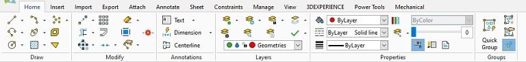
Similar to the ribbon tabs you see in Microsoft Office applications, these tabs organize the relevant tools for drafting or modeling by groups.
3. Graphics Area
This is where you’ll perform the actual drafting and modeling processes. It’s further sub-divided into:
- Palettes: This sub-section on the right allows you to manage drawing entities, properties, and resources.
- Shortcut menus: By right-clicking in the graphics area, you’ll see your options to execute.
- Command window: This is the sub-section below your project that you can issue commands to specify points and values as well as receive system notifications.
- Status bar: Below the command window is a row of icons called the status bar which gives you quick access to view and control drafting and coordinate display settings.
2D Drafting
Now that we know the basic UI, we can start drafting our ID tag.
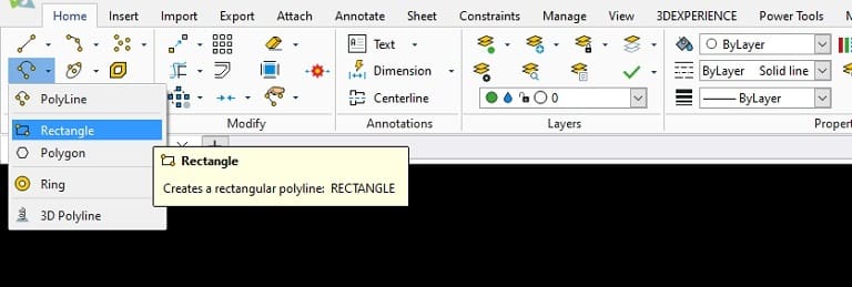
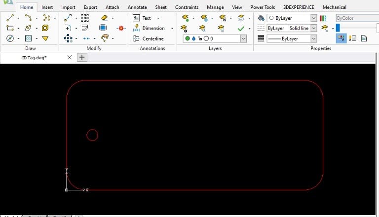
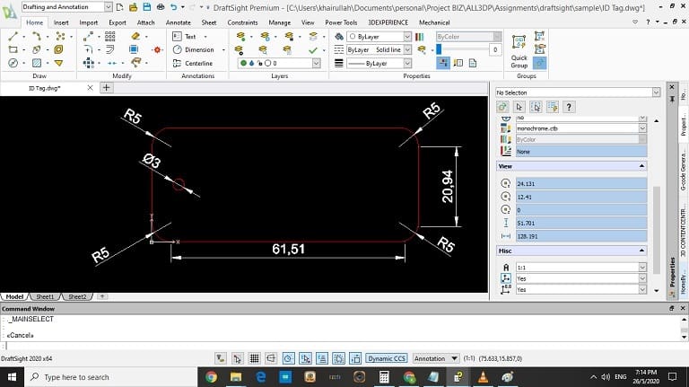
Step 1: Adding Shapes (Polylines)
Here, we’ll show you how to insert basic 2D shapes.
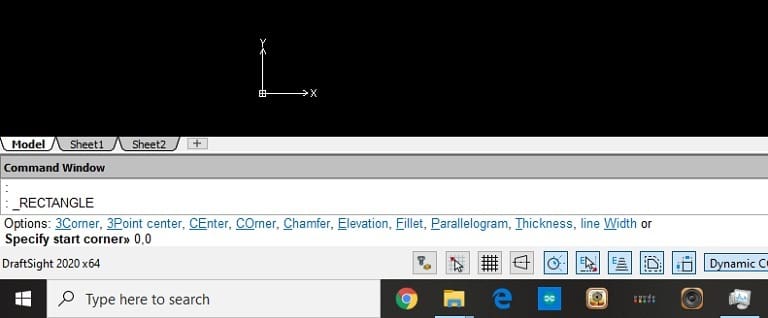
- Insert a rectangle from the Home/Draw tab (see image above).
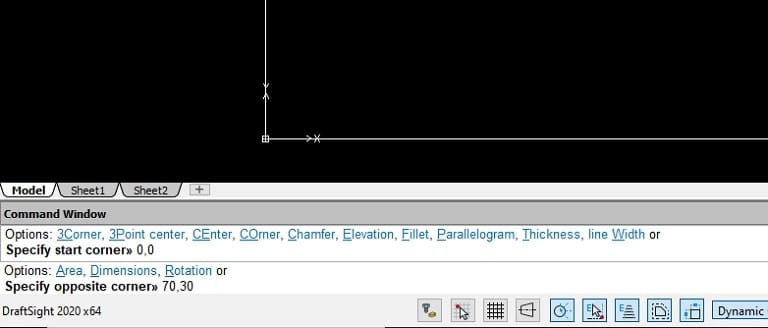
- In the command window, specify the start corner as “0,0” and press enter.
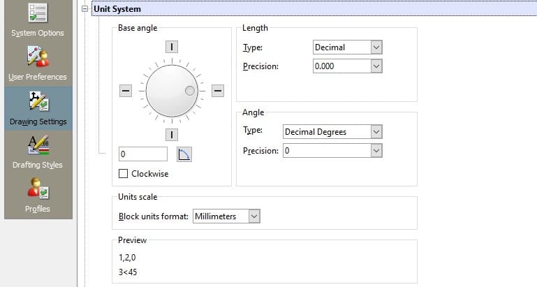
- Staying in the command window, specify the opposite corner as “70,30”. (This means that the rectangle shall have a length of 70mm, and width 30mm. Note that the default dimensional units are in millimeters.)
For users who prefer to use the Imperial numerical system, the unit of dimension needs to be changed.
- To view or change the unit of dimension, go to the Manage/Drawing tab and choose “Units”.
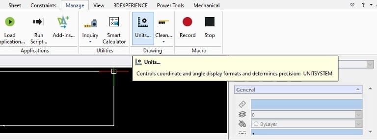
- The “Drawing Settings” panel opens for the user to specify the desired unit of dimension.
We’ll now continue with drafting the ID tag.
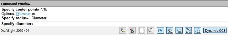
- Add a circle in the same manner as we added the rectangle.
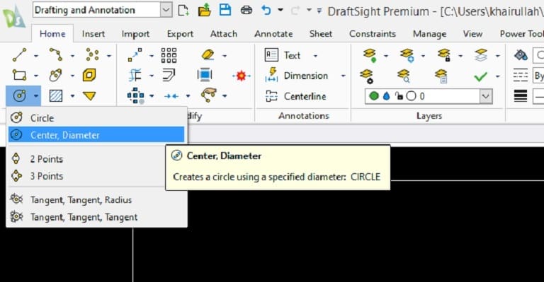
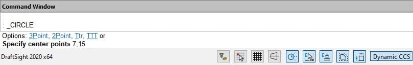
- To specify the center point of our circle, type in the command window, when prompted, “7,15”.
- Specify the diameter of the circle to be “3”.
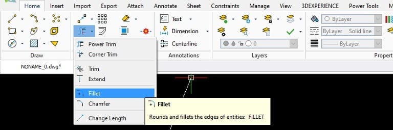
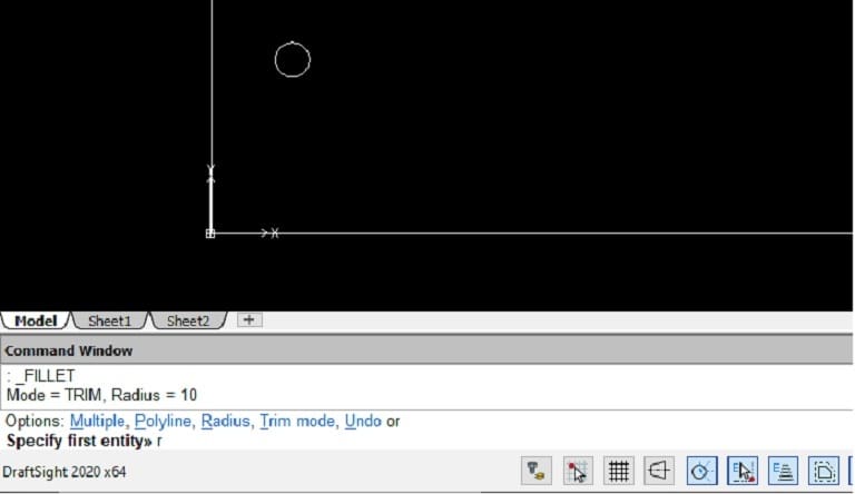
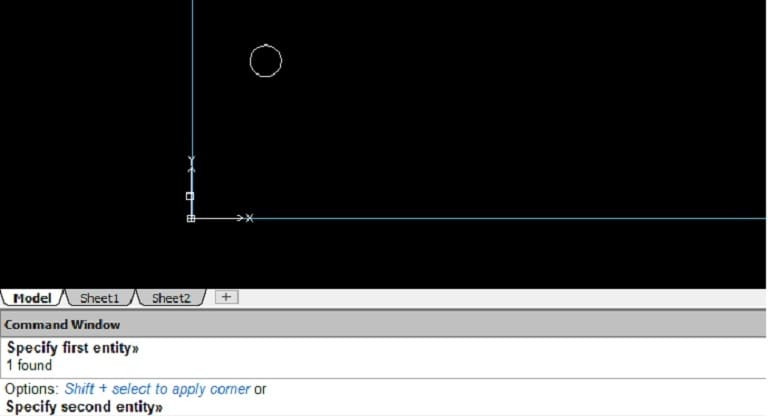
To make the corners of the rectangle safer, we’ll be filleting the edges.
- Select the Fillet option under the Home/Modify tab.
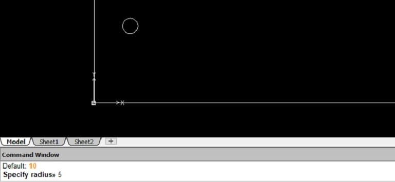
- Set the radius for the filet by entering “r” in the command window.
- Set the new radius as “5”.
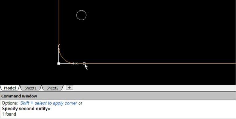
- Specify the first edge to apply the fillet.
- Select the second edge to apply the fillet. The corner will be filleted as shown.
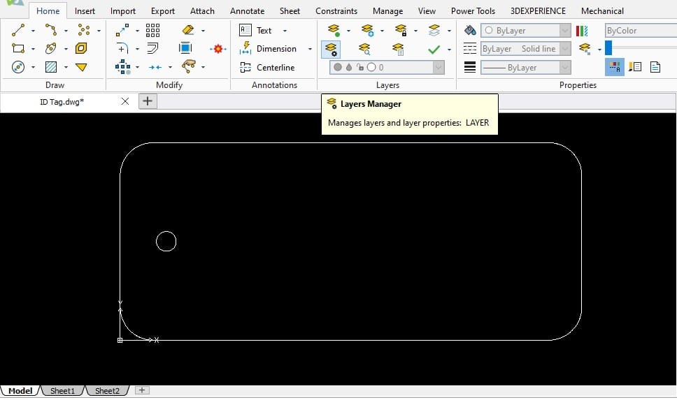
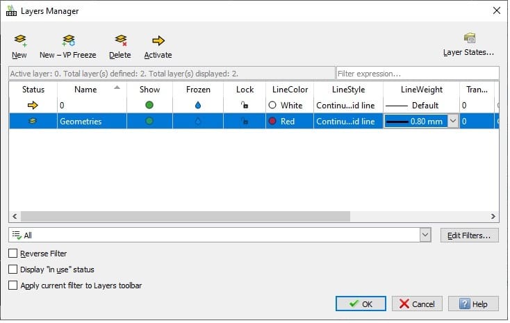
- Select the “Layers Manager” from the Home/Layers tab.
- You’ll see the Layers Manager pop up upon opening.
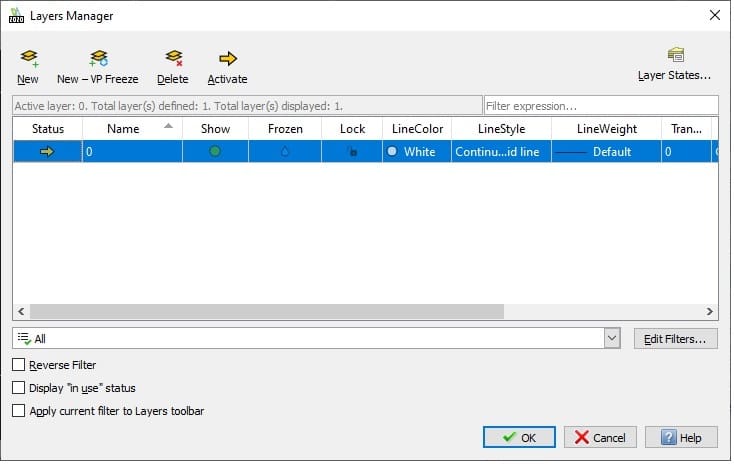
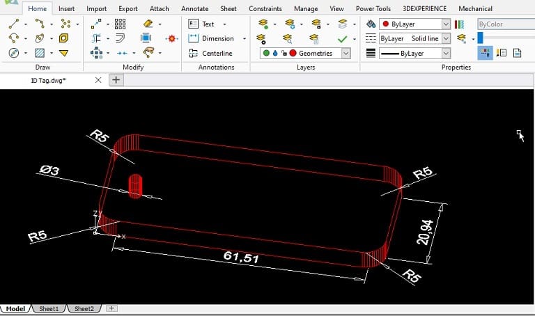
- Add a new layer and name it “Geometries”. This layer is for all geometrical drawings in our project. Set the “LineColor” to “Red” and “LineWeight” to “0.80 mm”.
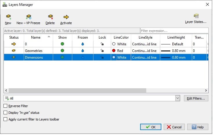
- Add another layer for all dimensions. Set it to “LineColor”: “White” and “LineWeight”: “0.80 mm”.
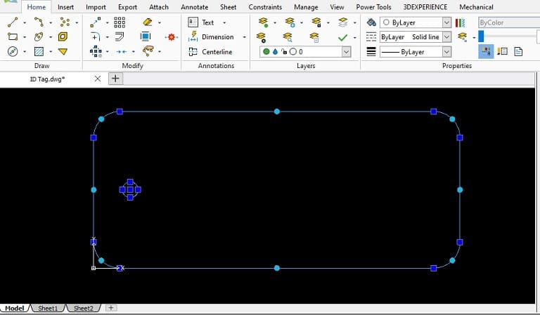
- Select the entities (rectangle and circle) to be assigned to the layers that you just added.
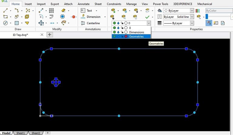
- With the geometrical drawing entities selected, click the layers drop-down box and select the “Geometries” layer.
- Complete the layer setting.
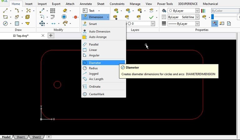
- Go to the Home/Annotations tab and select “Dimension”.
- Select “Diameter” from the drop-down menu to add dimension to the circle.
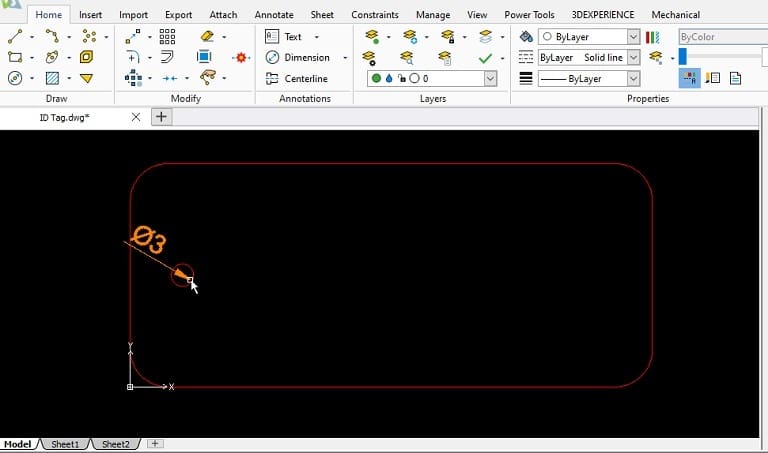
- Click on the circle and the dimension will be added. Move the cursor to position the text in the desired position.
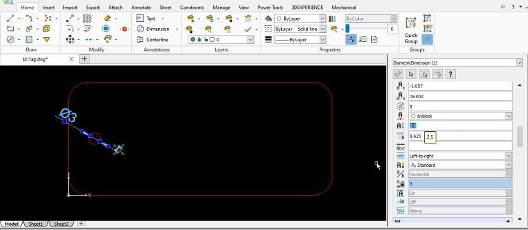
- Change the text size to “2.5” by selecting which dimension you wish to alter.
- Repeat for adding dimensions to the rectangle edges and fillets.
Step 2: Defining Layers
It’s good CAD practice to separate the “geometrical drawings” layer from the “Dimensions” layer. We’ll learn how to do this in Draftsight now.
Now the entities will have their properties set in the Layers Manager.
Step 3: Dimensioning
In this step, we’ll add dimensions to the design that we’ve made so far.
You can change the properties of the text as necessary by amending the properties dialog box on the right.
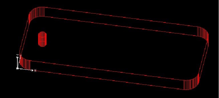
You’ve just completed a 2D drawing of an ID tag (finished drawing shown below)!
Next, we’ll transform our 2D drawing into a 3D model.
3D Modeling
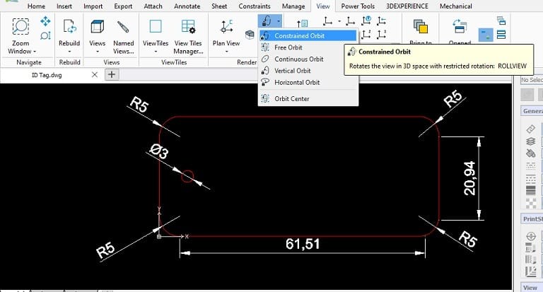
Step 4: Transform to 3D Model
- Go to the View/Render tab and select “Constrained Orbit” (see above).
- Select around the middle point of the entity. This is to set the point around which the entity will rotate in 3D space.
- Rotate the entity by clicking and dragging the drawing.
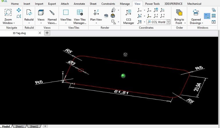
- To add depth, select the geometrical drawing and amend it in the “General” properties dialog box on the right.
- Set the depth to “5”.
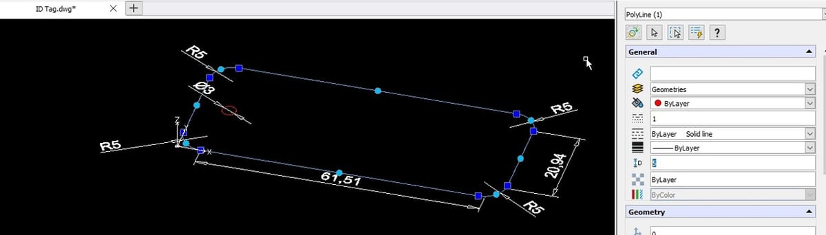
We’ve now completed the 3D model of our ID tag! Easy, isn’t it?
Exporting
Draftsight allows you to export your models in various formats, depending on your needs.
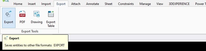
- To export, go to the Export/Export Tools tab and select “Export” (see above).
You should see the list of available formats for export. Select and you’re done!
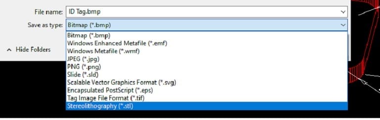
Now you can get to 3D printing! Enjoy exploring Draftsight!
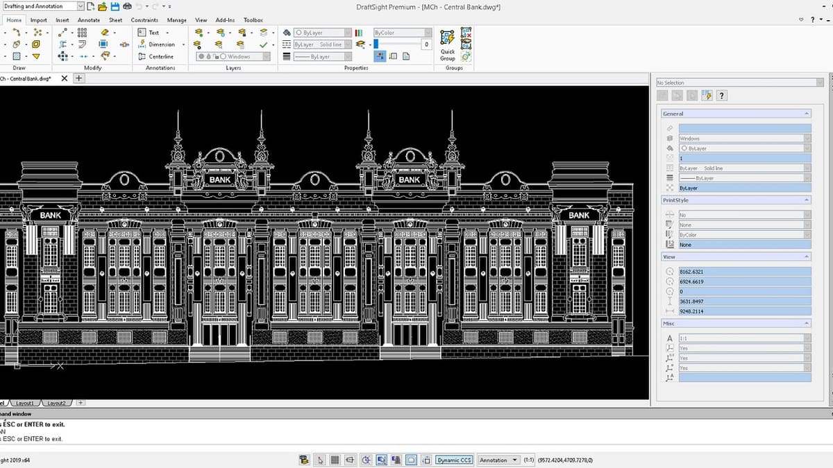
Lead image source: Draftsight
License: The text of "Draftsight Tutorial: 4 Easy Steps for Beginners" by All3DP is licensed under a Creative Commons Attribution 4.0 International License.