How to Edit STL Files in Fusion 360

Editing STL files in Fusion 360 has always been tricky. Find out what you can do with Fusion 360's mesh editing tools.
The STL format is arguably the most popular file type for 3D printing, especially for hobbyists and home use. It’s a lightweight mesh 3D model that’s simple to export and easy to share.
Most of the time, instead of creating your own STL files, you may find them online in repositories and forums, or even directly from companies’ websites that share their products’ 3D models. Because it’s someone else’s design, the model might not fulfill your exact needs. Instead, you’ll find something that’s rather similar and which requires a bit of tweaking and editing.
Even if you’re lucky enough to find the perfect STL model, it’s also possible that the file has some errors or imperfections that require mesh repair before it can be sent to the 3D slicer.
Additionally, if you’re 3D scanning an object, the resulting STL file will need, at least, a few post-processing operations. This is because scanning software collects point cloud data and converts it to an STL file, which in turn requires some model refinement tasks, like filling holes and preparing it for 3D printing.
So, no matter where the model’s originating, you’ll more than likely need 3D modeling software to make it printable – and here’s where Autodesk Fusion (formerly Fusion 360) comes in. This program, which possesses a versatile mesh environment, in spite of significant improvements over the years, still faces some challenges when it comes to STL editing.
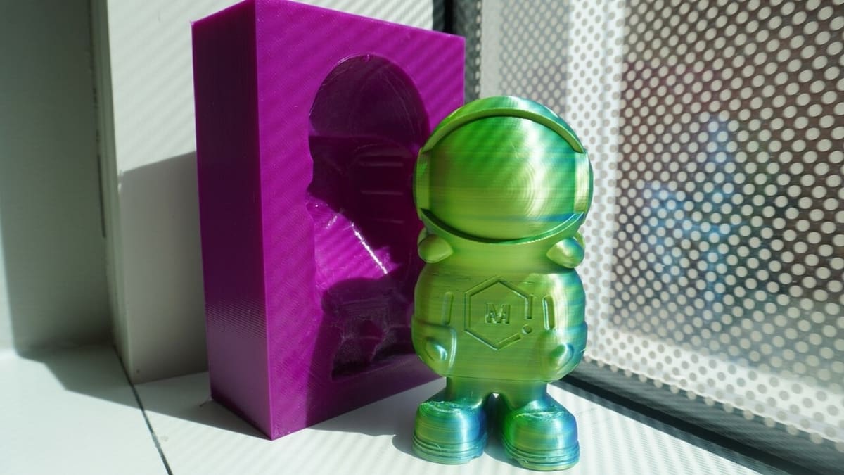
In this article, we’ll go over all the relevant details for editing STL files in Fusion, including the essential features and tools to do it, and will show you how to perform these mesh editing operations step by step. To do this, we’ll go over a brief tutorial on how to create a travel case for MatterHacker’s 3D Phil. But first, a bit more on Fusion and meshes.
Fusion 360 & Meshes
Fusion is a great computer-aided design (CAD) program for 3D printing, but it’s not comprehensive mesh-editing software like Blender or Meshmixer. This might be curious, given that the latter is owned by Autodesk and is no longer being developed or supported (but you can still download and use it), and most of its features have been included in Fusion. That’s not to say that Fusion doesn’t have plenty to offer, though.
According to the latest update (at time of writing) on mesh-editing tools announced in March 2024, Fusion users can now use the Fusion API (Application Programming Interface) to write programs using mesh-editing tools with the aim of automating the editing process. This is very attractive when dealing with repetitive operations.
However, for significant design changes, STL models still need to be converted to a solid CAD-friendly format. This means that the object acquires solid attributes, instead of being treated as a mesh, which behaves more like a surface. The user then gets complete control of the editing process with all of Fusion’s tools and features.
The conversion from STL to solid might not be as smooth as we would like it to be, depending on the complexity of the model. A high number of facets can make a conversion taxing on the software and hardware, even crashing Fusion altogether. This is why sometimes you’d be better off working directly with the STL file, especially if the adjustments are simple.
Fusion’s mesh-editing tools are basic but cover many necessities when working with STL files. Simple tasks like Scale, Plane Cut, and Combine are all present, as well as an automatic mesh-repair tool that Fusion borrowed from Netfabb. Let’s take a closer look at what you need to know about Fusion’s relevant STL editing tools.
Features & Tools to Know
Before anything else, we need to bring the STL file into Fusion. There are a few different ways to do it, but the “Insert Mesh” tool will allow you to position the model in the workspace and set the unit type (like millimeters or inches) since STLs lack this information.
This feature can be found under the “Insert” panel, but all the other tools for editing STLs will be found under the Mesh tab.
To start with the basics, if you need to run a quick check-up and correct minor issues, the Repair feature (in the “Prepare” panel) is the one to go for. Usually, Fusion lets you know the STL has issues as soon as it’s imported, and all you need to do is select the Repair tool and choose what to repair. Repair options include the “Close Holes” and “Stitch and Remove” actions, and once selected, the program will run them automatically.
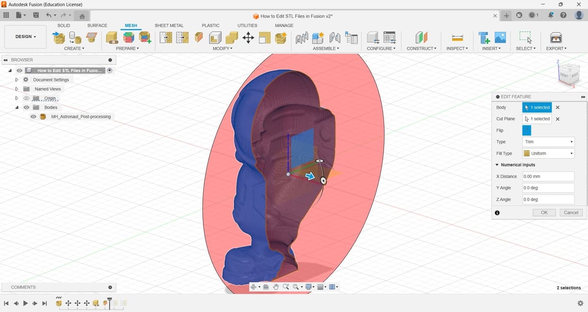
Plane Cut, found under the “Modify” panel, is also an important one. For example, you can use it to split big models into smaller parts so they can all fit within your 3D printer’s build space. You can also choose whether the model will be filled in automatically – patching the hole after cutting the mesh – or if it’s left as a shell. As the name suggests, you need a plane to perform the Plane Cut operation. This can be one of the three default planes (XY, XZ, or YZ), any planar face, or even a new plane. You can easily create a new one using the many options under the Construct tab.
As mentioned, if you need to modify the STL model more profoundly, it’s better to convert it to a solid. This is also how you can integrate STL models into your own modeled parts and projects.
For relatively simple models, there’s a good chance you can convert them directly. The conversion can be done by going to “Modify > Convert Mesh”, and you can choose whether to keep the transformation in the Design History timeline by selecting “Parametric”.
For finely detailed models or overly refined STLs, Fusion will warn you about the substantially large number of resulting facets. If you decide to continue, it will try to convert the mesh into a solid, but if the task becomes too expensive, computationally speaking, Fusion will freeze and, eventually, will abort the conversion. This is usually due to an increased number of facets making up the STL model that will make it nearly impossible to process.
The “Reduce” tool, also found in the “Modify” panel, can be used to reduce the number of facets in a model and therefore make the conversion to solid possible. You can select the percentage of reduction and also see a preview of the new faceted model before running the tool.
After editing and modifying the converted model, you can export it again to STL. In addition to STL (both Binary and ASCII), Fusion also allows users to export to different mesh formats like OBJ and 3MF.
Now that we’ve gotten our bearings a bit in terms of what can be done in Fusion, let’s take a closer look at how these tools can be used.
Importing the STL File
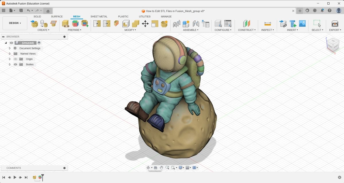
The very first step of editing a mesh in Fusion is, indeed, getting that STL file into Fusion.
- First, click on the Insert panel from the toolbar located at the top right of the User Interface (UI).
- From the drop-down list, select “Insert Mesh”.
- From the new window that will appear, click on “Select from my computer…”.
- Browse through your files until you find the desired STL file and click on the Open button.
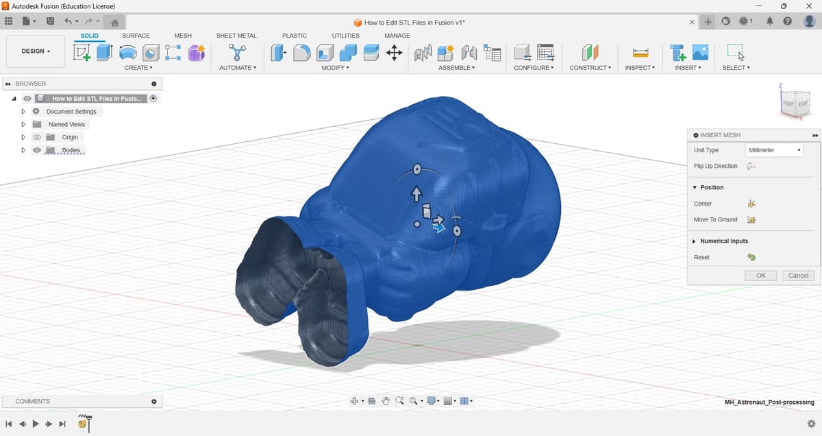
The STL file will appear in the main work area. However, it’s highly probable that the positioning and orientation of the mesh aren’t what you need. To correct that, you can use the translation and rotation arrows.
Additionally, you can opt for aligning the center of mass of the mesh with respect to the center of the Origin or place it above the XY plane. This is achieved by clicking on the “Center” or “Move To Ground” icons, respectively, which will be available in the “Insert Mesh” pop-up menu when you’ve added the model. If for some reason you need a new orientation, this can be easily accomplished in further steps using the Move/Copy tool (found under the “Modify” panel or clicking on ‘M’).
Closing the Mesh
From now on, we’ll be working with tools located under the Mesh tab. So, if you can’t find the tools we mention here, it’s probable that you’re on a different tab, like Solid or Surface.
That out of the way, let’s focus now on our mesh. Sometimes, the STL file you intend to edit will have open spaces, which translate to an open mesh once imported into Fusion. If the goal is to convert the mesh into a solid, you have to close that mesh. Otherwise, the result of the conversion will be a surface.
There are many ways to do so, and we will cover the easiest one, which requires using the Repair tool.
- Click on “Prepare > Repair”. A small window will appear on the right-hand side of the screen.
- Select the body (mesh) by clicking on any part of it, and make sure the “Stitch and Remove” option is selected in the Repair Type section of the Repair pop-up window. You can preview the changes by clicking on the corresponding box.
- To finish, just click on “OK”.
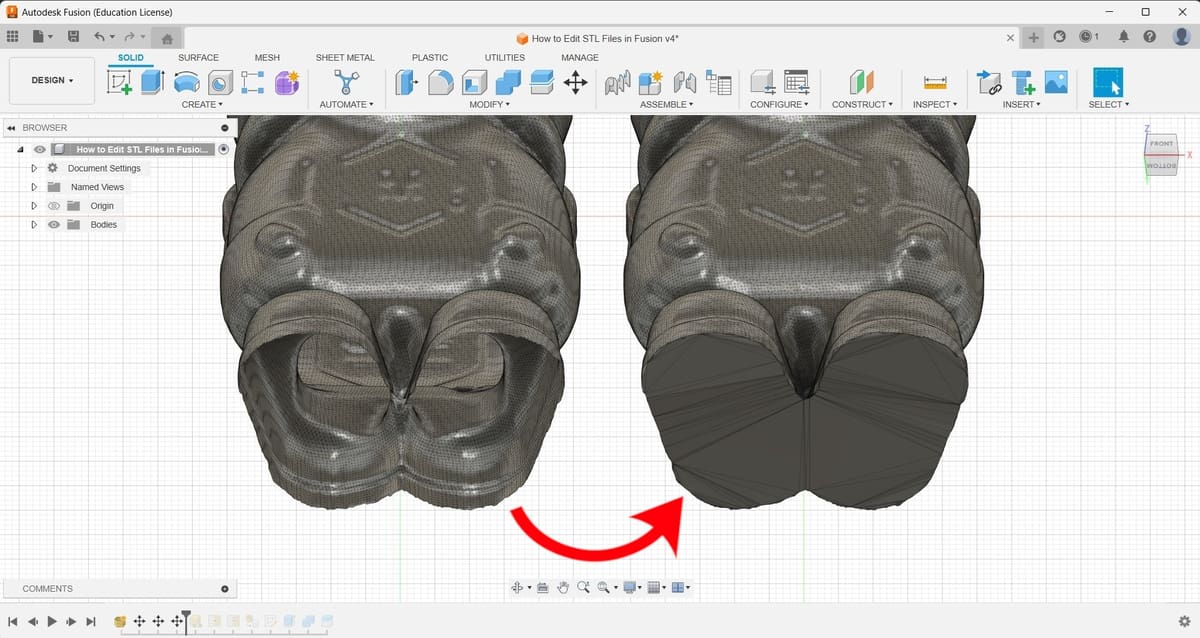
Fusion will automatically detect the open spaces and will try to close them in the most convenient way. In our example, we are using this tool to close the bottom of our model: the soles of the astronaut’s boots.
Simplifying the Mesh
Now that we have our mesh closed, it’s time to simplify it. This means that we’re going to reduce the number of planar elements – facets – that create the shape of our model. This is a critical step if we’re looking to convert our mesh into a solid body. As we explained before, more elements mean more computation when converting the mesh into a solid body. Hence, having fewer elements yields to a simpler, faster, and – most of the time – doable computation.
To achieve this goal, we will use the Reduce tool, which you can find under the Modify panel’s drop-down menu. You can also find its icon between the main ones shown in said section.
- Select the “Reduce” tool. Once you click on it, a small window will appear on the right-hand side of the screen.
- Select the mesh by clicking on it.
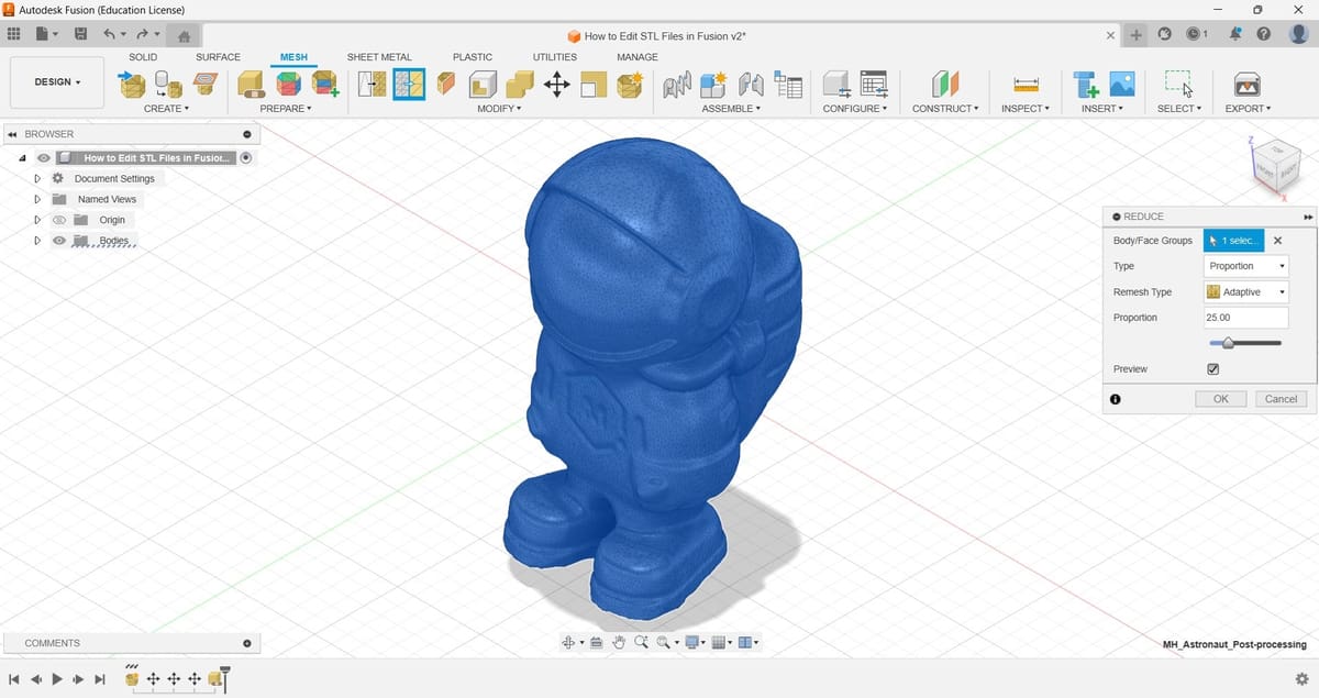
- Modify the desired parameters, although, except for “Proportion”, we suggest leaving the values as they are by default unless you’re more experienced or know exactly how the changes will affect the model.
- Increase or decrease the proportion percentage depending on how much you want to simplify the mesh. In our example, we kept the default value of 25 for the proportion and applied this operation twice. By doing this, we have reduced the number of facets from 270,144 to 16,884.
- You can enable the preview of the operation by checking the corresponding box.
As we said before, the smaller the number of elements, the easier the conversion from mesh to solid body. Just keep in mind that every time you perform this operation, you’re also reducing the level of detail of the original model, so make sure to find a midpoint between complexity and level of detail you’re comfortable with.
Smoothing the Mesh
An additional step before converting the mesh into a solid body consists of smoothing sharp edges. Determining whether this tool will be useful for you or not depends on the application you have in mind for the model. In any case, we’ll go over how to use it.
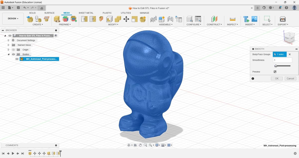
- Select the “Smooth” tool under the Modify panel. A small window will appear on the right-hand side of the screen.
- Vary the smoothness using the slide bar. The closer the number to 1, the more drastic the smoothing operation will be. Make sure to enable the preview to visualize the result before clicking on “OK”.
Unfortunately, Fusion doesn’t offer more options to carry out this smoothing process. Meshmixer includes a wider variety of tools and parameters to perform such operations, so if you have more demanding smoothing needs, you should consider using this latter program instead (at least for this step).
In our example, we won’t keep these changes since they aren’t necessary for our goal.
Converting the Mesh into a Solid Body
Up to this point, we’ve covered the basics of mesh editing in Fusion. That should be enough if you’re looking for small changes to an existing STL file.
However, if you want to apply more complex modifications – like extrusions, revolutions, or lofts – or if you intend to combine the STL file with other 3D models that you have created using Fusion – like integrating it to an assembly – then converting the mesh into a solid body is a mandatory step. Applications that benefit from these types of operations are those that focus on tailored solutions or customized, patient-specific devices, like the design of personalized prosthetics and ergonomic implements.
In any case, the steps to convert the mesh into a solid body are:
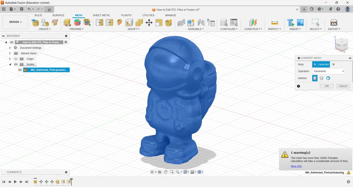
- Select the “Convert Mesh” tool from the Modify panel.
- Select the mesh.
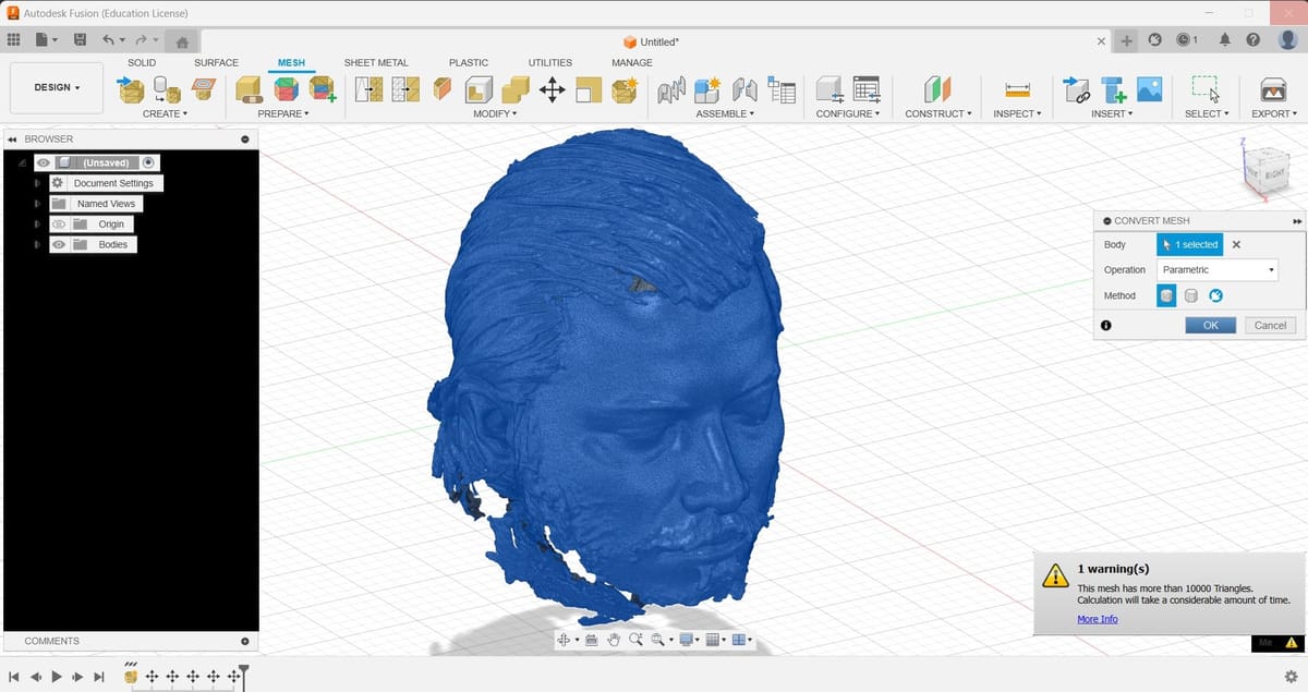
- Specify the type of operation and method you want to implement. We suggest keeping the default Parametric option for the Operation type and the Faceted option for the Method type.
Once you select the mesh, you may notice that Fusion shows you a warning message saying that the mesh has more than 10,000 triangles – facets – and that, as a result, the calculation will take a considerable amount of time. Depending on your computer’s processor, this can represent a problem, since Fusion might not be able to perform such an operation. If that’s your case, we suggest simplifying the mesh even more to reduce the number of facets before trying to convert the mesh.
Further Operations as a Solid Body
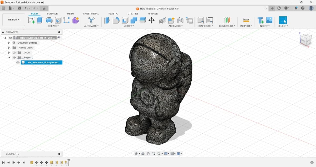
The path to follow beyond this point is up to you. For explanatory purposes, we’ll create a travel case for our little spatial friend. We’ll use the “Rectangle” feature from the Sketch environment and the “Extrude” and “Combine” tools from the Solid environment.
Let’s start by creating a solid box that can contain the astronaut.
- From the Solid tab, under the “Create” panel, select “Create Sketch”, which will slightly alter the UI as “Sketch Mode” has been entered. Click anywhere on the screen and you’ll be automatically in the Sketch tab.
- Create a rectangle (from the Create panel), then go back to the Solid tab and, from the Create panel, select the “Extrude” tool and apply it enough so that the rectangle covers the astronaut completely.
- From the “Extrude” pop-up box on the right of the UI, to avoid deleting the astronaut’s body, under Operation, select “New Body”.
- Subtract the astronaut’s body from the box using the “Combine” tool (Modify panel). The box will be our “Target Body” and the astronaut will be our “Tool Body”.
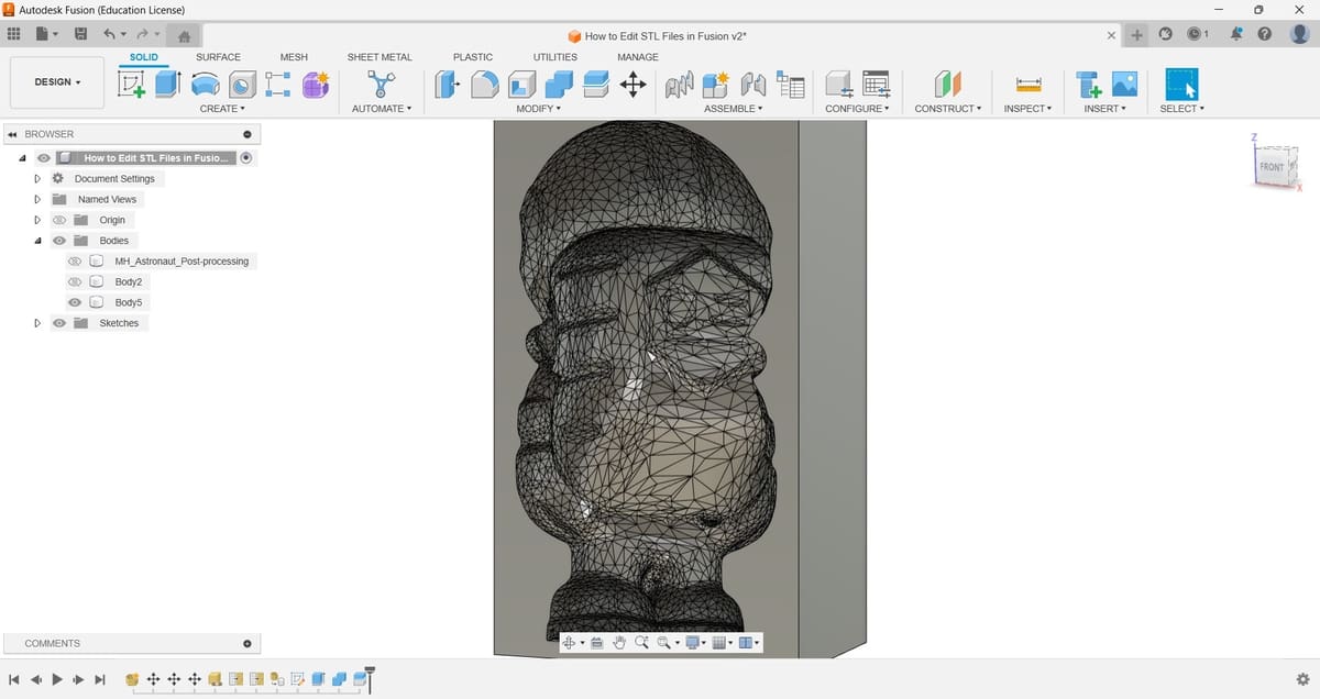
- Select the Cut option as the Operation type. This will result in a Boolean subtraction. Fusion will automatically show a preview of the operation, so you can have a clearer picture of the result.
- By default, the “Combine” tool deletes the tool bodies after executing, but that can be changed by checking the Keep Tools box.
- From the Modify panel, select the Split Body tool to cut the box in half. Select the box as the “Body to Split” and the XZ plane as the “Splitting Tool(s)”.
- Click “OK” to execute the operation.
Now that you know how to edit STL files in Fusion and how to convert them into solid bodies, go ahead and create as many cool inventions as possible. Don’t forget to share your results!
License: The text of "How to Edit STL Files in Fusion 360" by All3DP is licensed under a Creative Commons Attribution 4.0 International License.