How to Use the Esp32-Cam with Arduino IDE

With the Esp32-Cam, Arduino is the perfect match! Learn about how to get started running your Esp32-Cam with Arduino IDE.
Simply put, the Esp32-Cam is a microcontroller paired with a small camera that can be programed to take pictures or even timelapses and send everything over Wi-Fi. It’s ideal for IoT projects that involve wireless connectivity and image processing – for instance, a home surveillance system, a smart doorbell, or even a remote monitoring system for 3D printers.
In this guide, we’ll show you how to set up the development environment for Esp32-Cam board. Although Espressif (the manufacturer) has their own framework called “ESP-IDF” to program Esp32, it also supports the Arduino framework, which is more beginner-friendly. As it’s the simplest way to get started with the board, we’ll use the Arduino IDE to flash your very first program on Esp32-Cam.
Without any further ado, let’s get started!
What Is It?
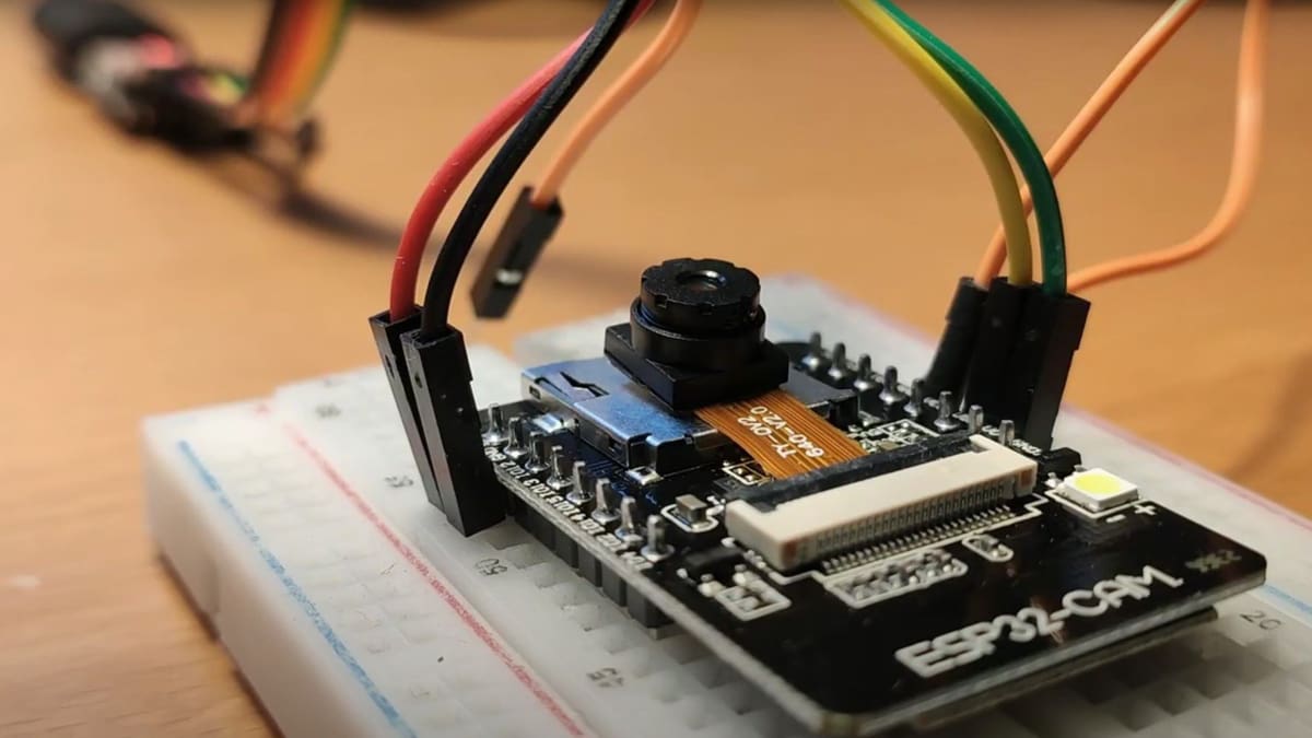
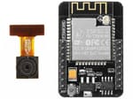
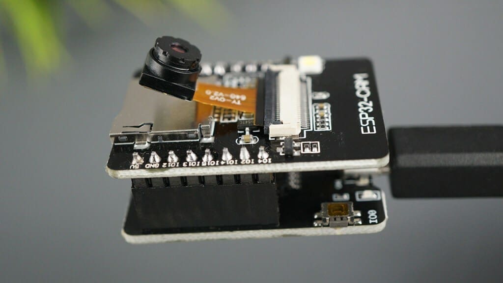
The Esp32-Cam is a development board that integrates an ESP32 microcontroller, a 2-megapixel camera, and a MicroSD card slot in a single package measuring about 27 x 40.5 x 4.5 mm. Priced around $10 to $20 depending on which variant you get, the development board is a very popular choice among hobbyists for its low price, compactness, and features.
The camera allows you to capture images and even has a small flashlight! The memory card slot makes it possible to store captured images along with other files. Moreover, as the Esp32 chip provides Wi-Fi and Bluetooth capability, you can send images to another device over Wi-Fi or Bluetooth. The combination of wireless capabilities, camera integration, and storage options make the Esp32-Cam a flexible, budget-friendly solution to explore the world of computer vision and IoT.
Unfortunately, the compact form factor does come with some trade-offs – the lack of a built-in programmer, for example. Unlike typical Esp32 development boards, the official Cam board requires you to use an external USB-to-Serial adapter to program it. Another caveat of the Esp32-Cam board is that the reset button (marked “RST”) is located on the bottom of the board. So, if you mount it on a breadboard, you won’t be able to reset it.
Applications
The Esp32-Cam is an excellent choice for projects like home surveillance, wildlife monitoring, or even object detection when offloading the processing to a web server. However, one of the most popular uses is creating time-lapse recordings of your 3D printing projects.
By positioning the camera to capture your printer’s build plate, you can document prints from start to finish, showcase the assembly process of complex parts, or quickly identify issues like filament jams or layer shifting if you’re monitoring the printer remotely.
For the remote monitoring part, this video from Canuck Creator should help you get started. Alternatively, if you have OctoPrint set up on your printer, you can use also use this plug-in to extend the Esp32-Cam interface into OctoPrint’s interface.
For setting up timelapse, check out this video from Bitluni’s Lab. Unfortunately, as of now, there’s no way to do remote monitoring and timelapse at the same time. If you find a solution, please share in the comment section.
Alternatives
Some companies have released their own takes on the Cam board that include an onboard programmer. For instance, Freenove manufactures one that’s a little bigger than the official Cam board. Its reset button is on top of the board, which is easily accessible. Unless compactness is absolutely needed, the Freenove board may be a better pick.
There are also more powerful variants, such as the Esp32-S3-Cam, which offer more features and better performance in terms of processing power. The Esp32-S3-Cam is quite different from the Esp32, so the instructions on how to use it with Arduino IDE may vary.
In this article, we’ll only be covering the Esp32-Cam development board.
Getting Started
To get your Esp32-Cam board up and running, you’ll need the following components:
- USB-to-Serial converter (FTDI programmer or equivalent): If your board doesn’t have an onboard USB programmer (hint: if you don’t see a USB port, it doesn’t have one), you’ll need an external USB-UART converter to program it. There are a lot of USB-to-Serial adapters available online, but we recommend going for the ones called “FTDI Programmer” or “FTDI cable” if possible.
- Alternative Option: If you have an Arduino Uno or Nano, you can repurpose it as a USB-to-Serial adapter by bypassing its onboard microcontroller and use it to program the ESP32.
- Jumper Wires and breadboard: Although not required, some jumper wires and a small breadboard will make it a lot easy to make temporary connections while programming the ESP32-CAM board.
- Arduino IDE: As we mentioned before, the Arduino IDE is the simplest way to get started with the Esp32-Cam board. If you don’t already have it, we’ll walk you through installing and setting up the Arduino IDE below.
Connection Guide
Since the wiring method for each kind of programmer is different, we’ll be going over all of them briefly.
FTDI Cable
The FTDI (Future Technology Devices International) cable is a USB-to-Serial converter that provides a simple way to connect your standard Esp32-Cam to a USB port on your computer. If you have an FTDI cable on hand, you can power the board with the 3.3V or 5V pins, plus Ground (GND) pins.
Pin GPIO0 determines the Normal mode or the Flash mode of the module:
- GPIO0 connected to Ground = Esp32-CAM in Flash Mode = You can upload the code
- GPIO0 not connected to Ground = Esp32-CAM in Normal Mode = The board executes the program
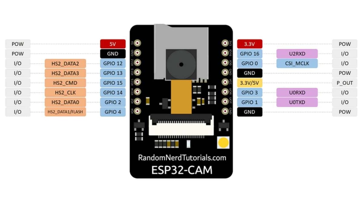
There are two serial pins, GPIO01 and GPIO03 (marked UOT and UOR), which can be used for serial transmission and to receive data with the UART (Universal Asynchronous Receiver-Transmitter) protocol.
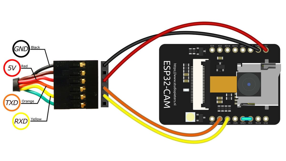
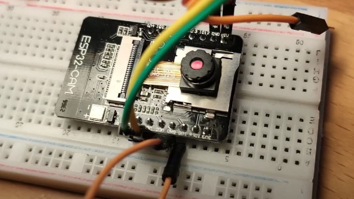
Other than the FTDI cable, you’ll need five jumper cables to connect the Esp32-Cam, as seen in the image above:
- 5V red cable connects to 5V on the board.
- GND to GND.
- TXD orange cable to UOT on the board.
- RXD yellow cable to UOR on the board.
- A jumper connects GPIO0 and GND (before uploading the code). Always remember to reset the board after changing the state of GPIO0. Connect and reset to upload, disconnect and reset to run the program.
Keep in mind that, because the reset switch is on the bottom of the board, it can be difficult to reach. To reset the board, you can simply disconnect and reconnect the 5V wire or the ground wire. Remember to keep the Arduino Serial Monitor open (Arduino IDE Menu > Tools > Serial Monitor) because it can give you important information and help you to debug your sketch.
FTDI Programmer
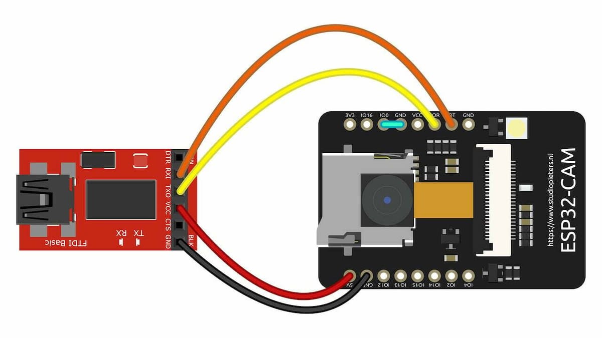
An FTDI programmer has exactly the same functionality as the cable – it’s also a USB-to-Serial converter, allowing you to simply connect it to a USB port on your computer. The difference between the cable and the programmer is the different pinout of the serial connection:
- Connect RX on the FTDI programmer to UOT on the board.
- Connect TX on the FTDI programmer to UOR on the board.
Since the Esp32 has a logic level of 3.3V, the FTDI programmer must be switched to 3.3V. Leaving it at 5V logic level may damage your Esp32.
Arduino Nano, Uno & Co
Maybe you don’t have an FTDI cable or an FTDI programmer at hand, but you may have an Arduino, be it a Nano, Uno, or other Arduino board.
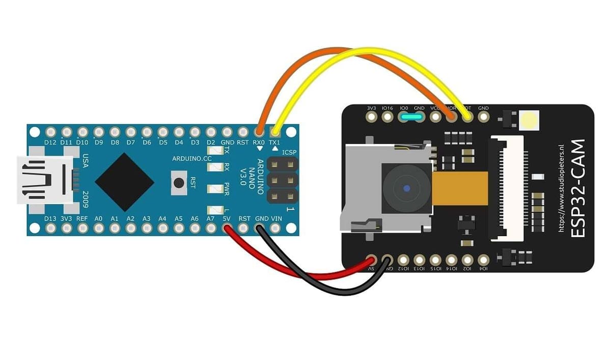
You can send data from the Arduino board to the Esp32-Cam serially by using the UART Communication Protocol, which has the following connections:
- 5V to 5V on the board
- GND to GND.
- TXD orange cable to UOT on the board.
- RXD yellow cable to UOR on the board.
- A jumper between GPIO0 and GND (before uploading the code).
The image above shows Arduino Nano connections.
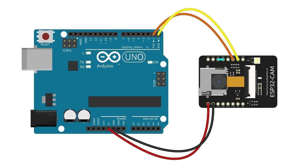
To connect an Arduino Uno, you can follow the same instruction as for Arduino Nano; you can confirm the Arduino Uno connections in the image above.
If you want to use another Arduino board you already own, you just have to make sure you are using the proper pins according to the numbered schema above.
To connect the Arduino board to your computer, you only need a USB connector (a mini USB cable is needed for the Nano).
Esp32-Cam MB Micro-USB Programmer
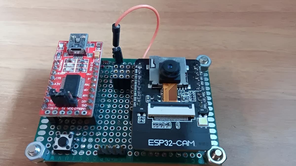
Esp32-Cam MB Micro-USB programmer is a shield for a standard Esp32-Cam board that adds a Micro-USB port. You just need to plug your board into the shield.
Once paired, as in the photo above, you only need a USB-micro-to-USB-A cable to connect to your PC or Mac and upload the code. That’s it. Easy, right?
You can buy either the MB shield alone or the kit, which includes the Esp32-Cam and the MB shield. To connect to your computer, you’ll need a Micro-USB cable.
Programming the Esp32-Cam
Once your Esp32-Cam is connected to the desired programmer, we can get to programming the Cam board.
Installing & Configuring the Arduino IDE
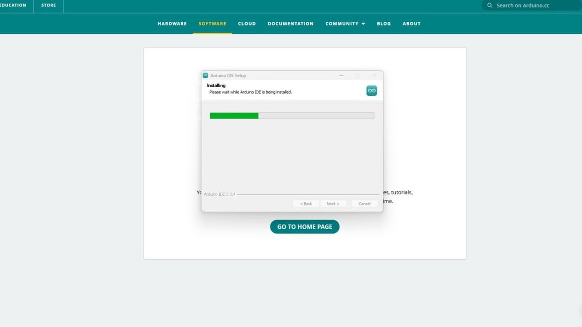
Let’s install the Arduino IDE first. Head to the official Arduino website and download the latest stable release of Arduino IDE for your operating system. Once downloaded, install it on your computer.
Then, we’ll need to add Esp32 boards:
- After launching Arduino IDE, open the Preferences dialog: “File > Preferences” on Windows/Linux or “Arduino IDE > Preferences” on MacOS.
- In the Additional Boards Manager URLs field, add the following URL: https://raw.githubusercontent.com/espressif/arduino-esp32/gh-pages/package_esp32_index.json
- Click OK to save your changes.
- Go to “Tools > Board > Boards Manager…“, then type “esp32” in the search bar. Something like “esp32 by Espressif” should pop up.
- Click the install button. Once it’s done installing, the Esp32 boards will appear in your Board options.
- Lastly, download the CH340 or CP2102 driver for the USB programmer (whether onboard or external). If you’re not sure which one your programmer uses, just download both. Windows 11 users don’t need to download the CH340 driver separately.
Uploading a Demo Sketch
Now that the Arduino IDE is configured and the Esp32 core is installed, it’s time to put everything into action. In this section, we’ll load an example sketch – a program written in the Arduino language – into the Esp32-Cam. The Arduino IDE will then translate this human-readable code into machine instructions for the microcontroller.
Once uploaded, the Esp32-Cam will run the code, connect to your Wi-Fi network, and provide a web interface where you can view live camera feed directly from your browser. Let’s get started!
Step 1. Select the Board and Correct COM Port
- Plug the Esp32-Cam into the USB-Serial adapter, then into your computer’s USB port. If the microcontroller has an onboard programmer, you can connect it directly to computer.
- In Arduino IDE, go to “Tools > Board”, then select “AI Thinker ESP CAM”.
- Next, go to “Tools > Port”, then select the COM port (on Windows) or /dev/tty device (on MacOS/Linux) associated with your USB-to-Serial adapter.
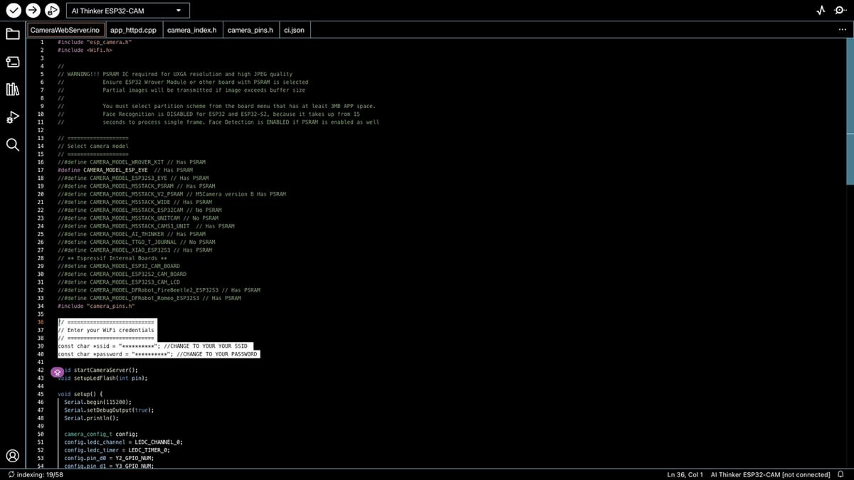
Step 2. Open & Modify the CameraWebServer Example Sketch
This example provides a fully functional web interface to view the camera’s feed directly from a browser.
- Navigate to “File > Examples > ESP32 > Camera > CameraWebServer”.
- Next, let’s update the Wi-Fi credentials in the sketch. Find the lines that define SSID and password, then replace the placeholders with your network’s SSID and password.
- Lastly, ensure the correct camera model is set for your board. Make sure any other #define CAMERA_MODEL_* lines are commented out.
Step 3. Entering Bootloader Mode & Uploading the Sketch
If your Esp32-Cam doesn’t have an onboard USB programmer, you need to enter bootloader (programming) mode manually by following the steps below. If it has one, feel free to skip directly to clicking the Upload button in the Arduino IDE.
- Connect a jumper wire from GPIO0 to GND on the ESP32-CAM. This tells the board to enter bootloader mode at reset.
- Press the board’s Reset button – or briefly unplug and re-plug the board’s power – to ensure it starts in the bootloader mode.
- Click the Upload button in Arduino IDE. During the connection process, if it hangs, press the Reset button again to prompt a successful connection.
Step 4. Running the Sketch & Viewing Output
- After the upload completes, remove the jumper wire between GPIO0 and GND.
- Press Reset once more to run the newly uploaded code.
- Open the Serial Monitor by navigating to “Tools > Serial Monitor”, then set the baud rate to 115200.
- Watch for the Esp32-Cam to print out its assigned IP address in the Serial Monitor. Note down the IP address.
Step 5. Accessing the Esp32-Cam’s Web Interface
- Open a web browser on a device connected to the same Wi-Fi network. This can be your computer.
- Enter the IP address you saw in the Serial Monitor into the browser’s address bar, then hit Enter.
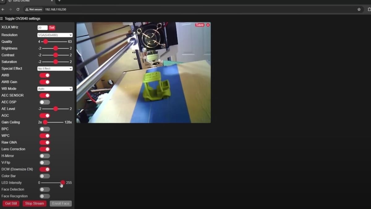
- The CameraWebServer page should load, allowing you to adjust camera settings, start the video stream, and capture images.
With these steps, you’ve successfully configured the Arduino IDE, uploaded the CameraWebServer example, and accessed the Esp32-Cam’s live feed.
Uploading Code Over the Air
Perhaps a physical connection won’t cut it and you need a remote setup. Maybe you have a lot of devices running the same software, or it might be difficult to make a physical connection to your board. Over-the-air (OTA) or Firmware-over-the-air (FOTA) updates come to the rescue.
There are many ways to implement OTA on generic Esp32s, but as the scope of this article is to give you the basics, we’ll concentrate on basic-over-the-air.
So, to implement Basic OTA, start Arduino IDE and follow these steps:
- Make sure the ESP32 boards have been installed successfully on Arduino IDE. If you haven’t done so yet, see the section on installing and configuring the Arduino IDE section above.
- Next, we’ll select the board. Go to “Tools > Board > ESP32 Arduino”, then select “ESP32 Wrover Module” – not Esp32-Cam.
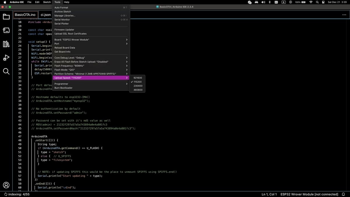
- Set the following parameters under “Tools”:
- Upload Speed: 115200
- Flash Frequency: 80 MHz
- Flash Mode: QIO
- Partition Scheme: Minimal SPIFFS
- Core Debug Level: Debug (it can be helpful)
- Port: Choose the proper serial port
- Open the Basic OTA example sketch by navigating to “File > Examples > ESP32 Wrover Module > Examples for Arduino OTA > BasicOTA”
- Add your Wi-Fi SSID and password as we did above in Uploading the Demo Sketch section. Then, save the sketch.
- Upload the sketch to your Esp32-Cam.
- Next, let’s check whether the server has started successfully. We can do this by confirming that the MAC address of your Esp32-Cam board is being displayed. Open “Tools > Serial Monitor”. The last message should read something along the lines of “begin(): OTA server at: esp32-4417937c9080.local:3232”, where 4417937c9080 is the MAC address of your Esp32-Cam board.
- After that, you can choose the network ports that will appear in the “Tools > Port” menu (see Step 1 in the section Uploading a Demo Sketch).
To use OTA in your sketch, you need to keep the basicOTA structure and just add your code in the four basic sections of an Arduino sketch:
- The comment section
- The variables section
- The setup section
- The loop section
If you need a refresher on Arduino sketches, check out this overview.
Happy OTA upload!
Troubleshooting
The Esp32-Cam board does come with its fair share of quirks and issues, some of which can be quite time-consuming to figure out. Fortunately, there’s pretty good community support for Esp32, so you should be able to find solutions for most of them online.
Here goes a troubleshooting guide we have prepared to help with frequently encountered issues:
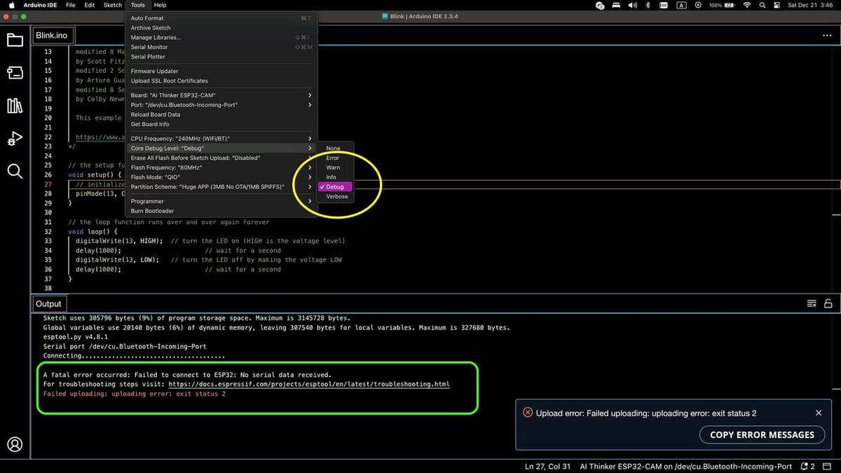
Failed Uploads or Connection Errors
If you’re getting errors like “Failed to connect to ESP32: Timed out” or the upload process stalls, it’s often due to the Esp32-Cam not entering the correct bootloader mode.
Solutions
- Check your wiring: Make sure your USB-to-Serial adapter’s TX is connected to the Esp32-Cam’s U0R (RX) pin and USB-to-Serial adapter’s RX to Esp32-Cam’s U0T (TX), and that you’ve connected GND to GND and 5V or 3.3V to the appropriate power pin.
- Update your USB-to-Serial drivers: Some USB-to-Serial chips (like CH340 or CP2102) may require driver updates. Install the latest drivers for your operating system, then try again. The drivers should be installed regardless of whether you’re using external programmer or onboard programmer, as both use those drivers.
- Enter flashing mode: The Esp32-Cam should automatically go into flashing mode while uploading the code. However, if for some reason it doesn’t, try tapping the on-board reset button right when Arduino IDE is connecting to the board – not before and definitely not after.
- Use a different USB cable: Sometimes, lower quality USB cables don’t work well with Esp32s, so changing the cable may help. Try to use a decent cable that’s not too long (less than 1 meter).
Boot Mode Errors or Garbage Output on Serial Monitor
Sometimes, the Esp32-Cam fails to boot or outputs unreadable characters on the serial monitor due to incorrect baud rates, wiring issues, or not exiting programming mode properly.
Solutions
- Set the correct Baud Rate: Start with a baud rate of 115200 in the Serial Monitor. If you still see gibberish, try 74880 baud, which is the default bootloader rate on some Esp32 boards. This can help you see debug messages and understand what’s going wrong.
- Double-check your pins: Make sure GPIO0 is released (not grounded) and that the board is reset after programming to ensure it boots normally.
- Check your power supply: If the Esp32 prints something like “Brownout detector was triggered”, that means it could not start up due to too low voltage. If your Esp32-Cam has other components (such as sensors) connected to it, check if there’s enough power for everything. If you’re only using the Esp32-Cam board without any peripherals, try using a different USB cable.
Camera Not Found or Initialization Errors
If the camera module isn’t detected or fails to initialize, it may be due to incorrect code settings, loose connections, or hardware incompatibilities.
Solutions
- Verify camera connections: Ensure the camera ribbon cable is firmly and correctly seated in the connector. The camera should not be loose, and the cable should be oriented correctly.
- Check code settings: Confirm that the camera model defined in your code (e.g.,
CONFIG_OV2640_MINI_2MP) matches the actual camera. The camera should have the model labelled somewhere on it. - Try a different power supply: Some cameras require stable voltage and enough current. Switching to a dedicated 5V supply rather than relying on the USB-to-Serial adapter’s power can help. Disconnect the 5V pin of Esp32-Cam from the USB-Serial adapter and connect it to your external power supply; ground should be left connected to the USB-to-Serial adapter. Make sure to connect the ground of the external power supply to the Esp32-Cam as well.
Unstable Wi-Fi Connection or Poor Image Quality
Weak Wi-Fi signals or insufficient lighting can result in poor image quality or connection instability.
Solutions
- Try different locations: Moving the Esp32-Cam closer to the Wi-Fi router should help with signal strength. If that’s not an option, try moving it closer to the ceiling.
- Adjust lighting and focus: Improve ambient lighting conditions or manually adjust the camera’s focus by gently rotate the lens to enhance image clarity.
- Reduce image resolution or frame rate: Using lower resolutions or frame rates can improve reliability, especially if your Wi-Fi signal is weak.
- Use an external antenna: If your Esp32-Cam board supports an external antenna, attaching one can significantly improve signal strength and reliability.
License: The text of "How to Use the Esp32-Cam with Arduino IDE" by All3DP is licensed under a Creative Commons Attribution 4.0 International License.
CERTAIN CONTENT THAT APPEARS ON THIS SITE COMES FROM AMAZON. THIS CONTENT IS PROVIDED ‘AS IS’ AND IS SUBJECT TO CHANGE OR REMOVAL AT ANY TIME.