Fusion 360 & CNC: All You Need to Know

Fusion 360 is a highly recommended tool for CAM. Read on to find out how to use Fusion 360 for CNC and other types of manufacturing!
Fusion 360 is a popular CAD program from the company Autodesk. It’s a well-loved tool that allows users to plan the complete design and manufacturing process within a single program. It has features for modeling, animation, simulation, and manufacturing technologies like 3D printing and CNC machining.
Fusion 360 has vast applications in industrial settings, but it’s also one of the most popular choices for hobbyists thanks to its affordable price and complete suite of tools. It has a free, somewhat limited version for personal use, as well as a full version for commercial use, costing just under $500 per year.
Fusion 360 was originally released in 2013 and quickly became popular because of its completeness, yearly updates, and not-too-steep learning curve. Even if you do your modeling in another program, Fusion 360 is a popular choice for the CAM process because its interface is more modern and aesthetic than that of many free CAM programs. It’s also very graphic, making it easy for even new users to understand.
Applications
Fusion 360 is intended for modeling single machine assemblies. This means it’s an ideal program to model things like a turnstile or a milling machine, but not to design a whole manufacturing plant, taking into account architecture, floorplans, and so on. For those kinds of applications, software like AutoCAD would be more suitable. However, for the design of the individual parts of a machine and its assembly, Fusion 360 is the perfect tool.
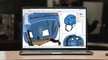
Moreover, Fusion 360 doesn’t only allow you to model parts of a machine and assemble it, but you can also make blueprints, simulate forces and strains to verify dimensions and materials, and animate the working process to make sure it’s correct.
Fusion 360 is especially used by people who work in manufacturing, due to its comprehensive CAM toolsets. Particularly for CNC machining, Fusion 360 is also the go-to choice for many hobbyists.
Fusion 360 for CAM
Many users prefer Fusion 360 for CNC because even the free, personal use version includes access to CAM tools. Users also prefer Fusion 360 because it has a more user-friendly and organized interface, especially compared to some of the free alternatives that look quite dated and don’t have as many functions.
There are many suitable programs that are more designed for industrial use, which take a bigger toll on your computer’s performance and are generally more expensive. This makes Fusion 360, in contrast, especially attractive for hobbyists or for personal projects.
Moreover, an additional advantage of Fusion 360 that you don’t get with many CAM tools is that you can create a design from scratch and then, without needing to export and import, switch over to CAM in the same program. This saves time, is more practical, and offers less chance of files corrupting when switching between programs.
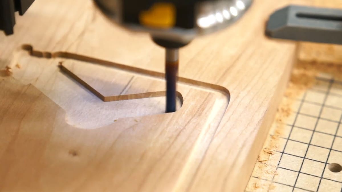
Additionally, Fusion 360 has CAM-specific tools to make the CNC process more efficient. For example, you can preview the cutting process beforehand, to avoid mistakes and wasted material, without needing additional simulation software.
Fusion 360 also has a G-code editor so that you can further tweak your G-code. It’s very graphics-oriented so you don’t need to be an expert on the technical side. Even when setting up your tool, you’ll be shown diagrams of what each measurement represents, so you’ll know what the program is asking.
Additionally, being an Autodesk product, you can install add-ins from the Autodesk AppStore which will further enhance the manufacturing experience.
Basic Workflow
1. Procuring a Model
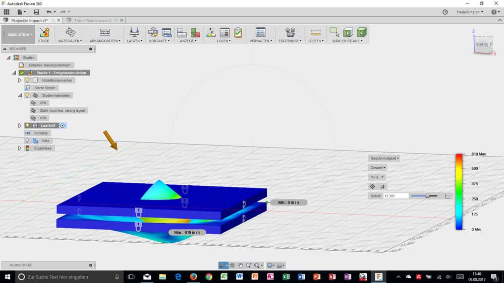
Fusion 360 is organized into workspaces, which are default layouts to display the most useful tools for each function.
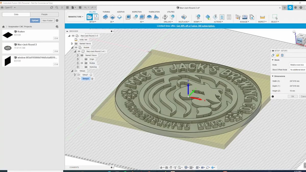
The obvious first requirement is a model that you want to create. Modeling is done in the Design workspace, or if you have a design already made in different software or downloaded from a repository, you can import it in the Insert section of the design workspace.
We’re focusing on the process of preparing for CNC, so we’ll assume you already have a model and are ready to jump to the CAM process.
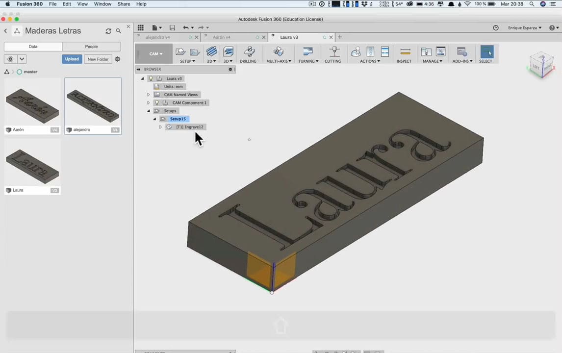
2. Choosing an Operation
With your model ready, switch over to the Manufacture workspace to set up your machine. Here, you’ll see 2D and 3D operation options. 2D means you’ll always be working at the same height (it’s possible to change heights, just not at the same time as moving in the XY-plane). 3D means you’ll vary height as you move horizontally, usually for curves.
To set a toolpath, you first have to choose what operation you need. There are many according to what you want to do, but the most basic one in CNC is 2D engraving. It’s also worth mentioning that you can do several different operations on a single model (as long as your machine can do them).
3. Setting Up Your Tool
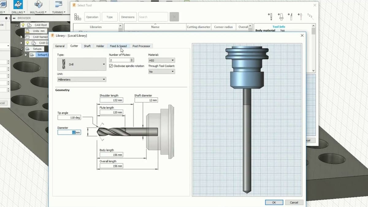
Once you choose an operation, a menu of many options will appear. The first thing you need to do is set up your tool. If it’s your first time working with CAM, you’ll have to prepare your “virtual” tools so that they match the physical cutting tools you have for your machine. Fusion 360 has default tools, so you can see if they match the ones you have, or you can make custom ones. We also recommend saving your tools with easy-to-remember names so that they’re easy to use later on.
Additionally, prior to working on an actual model, you should figure out settings like spindle speed, surface speed, and so on, which are asked in the first tab, corresponding to tools, to learn what works and what doesn’t with your machine.
4. Selecting a Toolpath & Stock
The next step is to select the toolpath. This is very easy, you only need to hover over the lines of the model you wish to cut and select them with a left-click.
The next tab is referent to the stock, which is the original block of wood you’re going to cut. Here, you have to indicate the height and depth, with an offset you want. On the next tab, you have to choose the passes, which is also very straightforward. You should indicate the number of step-downs and the depth of each, for the toolpath your machine will follow.
Finally, the last tab, called Linking, refers to some extra settings about what your tool does while it’s not cutting and where it goes in from. These options include advance speed and advance offset, which is how much it should separate vertically from the stock.
5. Preview & Final Touches
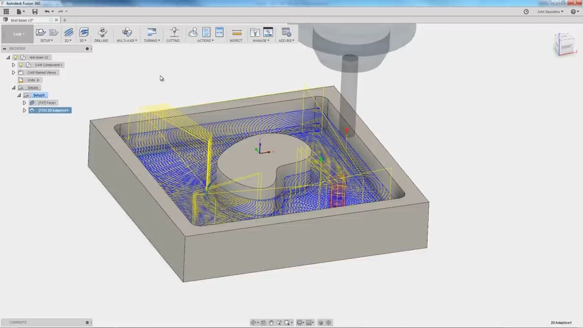
With all the instructions set, before exporting your G-code, it’s good practice to watch the simulated cutting process generated by your settings to check for mistakes and things you want to add. You can simulate by going to the Actions section of the toolbar and selecting Simulate.
Once you’re satisfied with your work, it’s time to export the G-code in “Actions > Postprocess”. You can directly open it, modify it, and check it the Fusion 360 G-code viewer.
Now that the G-code is done, all that’s left to do is load it into your controller software and cut away!
License: The text of "Fusion 360 & CNC: All You Need to Know" by All3DP is licensed under a Creative Commons Attribution 4.0 International License.