Fusion 360 Designing: How to Get Started Modeling

Intimidated by the learning curve of Fusion 360 modeling? Don't be! Follow along with our tutorial to create your own model from scratch.
If you’re into 3D printing or maker projects in general, you’ve probably heard of Fusion 360. Released in 2013 by Autodesk, Fusion 360 has become one of the favorite tools for 3D modeling hobbyists and beginners alike.
And that popularity may be for several reasons. For starters, it’s a professional-grade CAD program that offers free, limited licenses for non-commercial uses. It’s also a cloud-based program that allows projects to be stored online, facilitating team collaboration.
But perhaps most importantly, the software is packed with additional functionality, like CAM and CAE modules, photorealistic 3D rendering, a built-in 3D slicer, and even sophisticated design tools like topology optimization and generative design.
In summary, Fusion 360 offers many high-end solutions at an accessible cost. It should be your best bet if you’re looking to step up your game with new 3D modeling skills. And to help you with that, we’ve come up with a comprehensive tutorial on how to get started.
So get yourself some coffee (or tea) and follow along with us!
Downloading & Setup
Let’s start by getting the software on your computer. Fusion 360 is available for both Windows and MacOS, but it might be a good idea to check the system and hardware requirements before moving on. Currently, the program isn’t available for Linux, but there are a few workarounds for Unix users.
Now, let’s talk about licensing. Fusion 360 offers free, educational licenses for students and educators, so make sure to take advantage of this if you’re eligible!
You can also get a personal license for free. You just need to sign up for an account on Autodesk’s website and activate it to download the product. The free version has access to all of the most important features related to 3D modeling but can only import and export a few file formats (STL included!).
Most additional functionality packages, like 3D rendering, simulation (CAE), and advanced design tools are restricted to full licenses, although basic CAM for machining is available with free licenses.
The installation process is trivial, so once everything is ready, launch Fusion 360 and enter your Autodesk credentials. We’re good to go!
Understanding the UI
Let’s take a few minutes to better understand Fusion 360’s user interface (UI). It might look a bit intimidating at first, but it’s actually very intuitive once you get used to it.
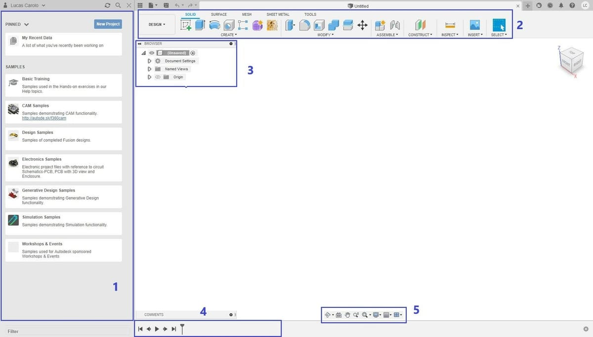
With Fusion 360 launched, your screen should look something like the picture above. At the very center and occupying most of the screen is the main viewport, where all the 2D and 3D design takes place.
Let’s walk through some of the main areas of the UI:
- Data panel: Where all the projects and designs can be managed and accessed. This is also where you can upload local models to the cloud and share projects and folders with other users.
- Toolbar: Located across the top of the screen. It displays a selection of the main functions used to create and manipulate models. The shortcuts displayed on the toolbar are all customizable. Clicking on the drop-down arrows will display all possible commands available in each tab and category.
- Browser: Located in the top left of the viewport. It lists all your components, bodies, and construction planes all in a file tree structure. You can select items simply by clicking on their names and rename them by double-clicking. Use the triangles on the left to open or collapse folders, and the lightbulb to toggle the visibility of bodies and planes.
- Timeline: The design history timeline at the bottom is a crucial part of Fusion 360, setting it apart from other CAD software. It contains a running list of operations executed when creating or manipulating your model. This lets users see exactly how each model was made, roll back the timeline to any point they wish, and make edits and additions to features, as needed.
- Navigation bar: These tools let you toggle the display settings and manually navigate the view. There are some useful shortcuts for this with a mouse, and we recommend trying them out to navigate around the 3D space:
- Pan: Middle (wheel) mouse button
- Zoom: Scroll up/down
- Orbit: Hold control + middle (wheel) mouse button
Creating a Model
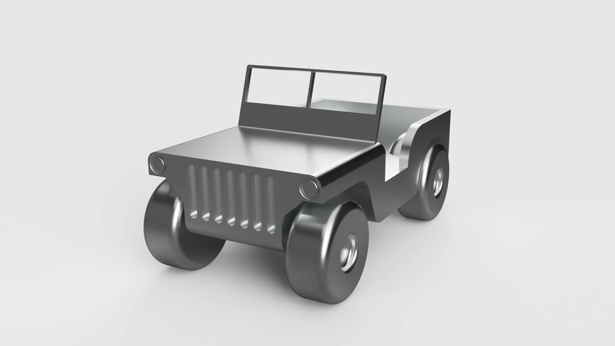
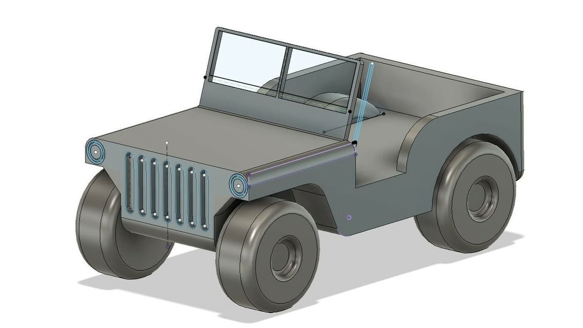
To demonstrate some of the essential Fusion 360 modeling principles, we’ll create a simplified model of an off-road vehicle. Generally speaking, the 3D modeling workflow often starts with one or more sketches that are then transformed into 3D solids, which can then be further manipulated.
There’s a considerable number of features and tools available in Fusion 360. And while we’re only going to cover the most basic ones, they’re more than capable of creating many different types of models and definitely enough to get you started with Fusion 360.
One thing before we start: In this tutorial, we’ll be using the metric system, but feel free to use any units you wish. (It may just be trickier to follow along.) To change the default dimension units of Fusion 360, do the following:
- In the top right corner, click on your account button indicated by your initials.
- Go to “Preferences > Default Units > Design”.
- Choose your preferred unit. We’ll be using millimeters (mm) for this tutorial.
Part 1: Sketching
The Sketch entity is one of the most important features in any CAD program. It’s basically a 2D drawing that serves as a base or template for three-dimensional transformations along the way.
With that in mind, it’s only fair that we start by exploring the Sketch and some of its tools. Let’s begin by drawing a 2D profile of the main body, or chassis. To do that, we’ll first need to select a surface or one of the starting planes to draw a simple rectangle.
Rectangle
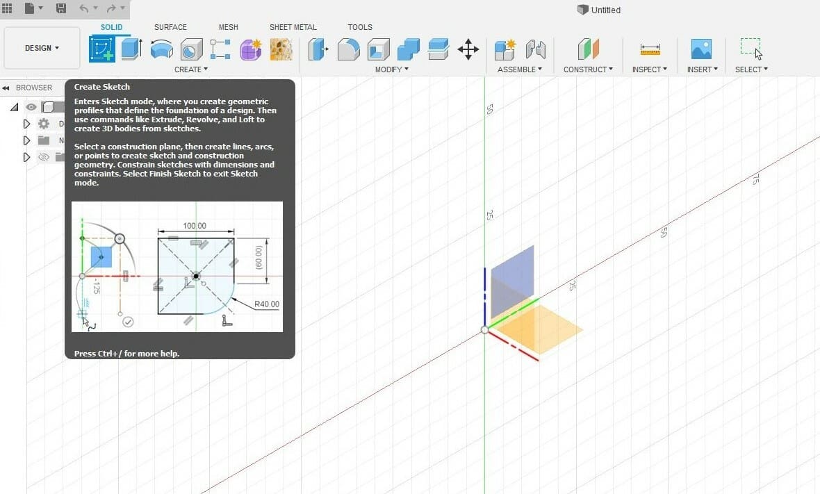
- Click on “Create Sketch” and select the YZ plane as shown in the image above. This is where our 2D sketch will be made.
- Select the “2-Point Rectangle” tool in the top toolbar and click on the origin within the sketch plane.
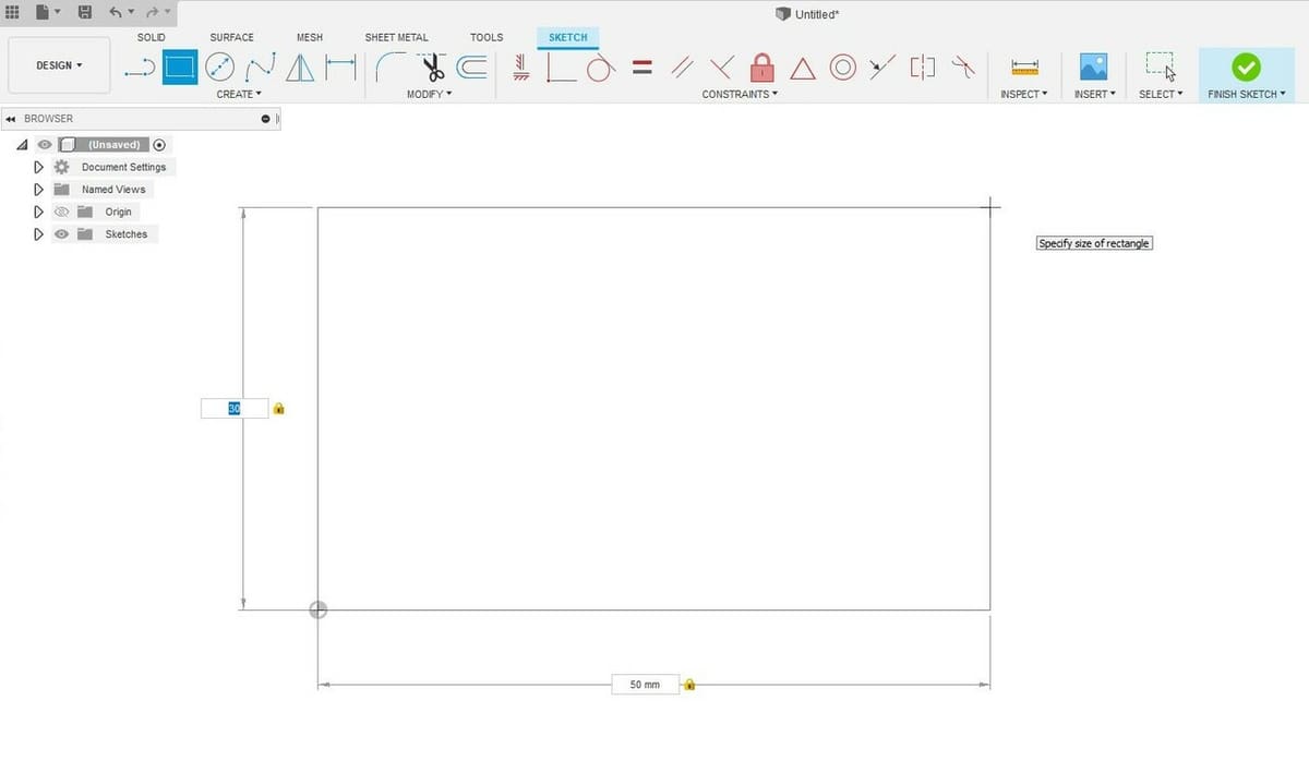
- Note that you can dimension the rectangle by either hovering the mouse or inputting the dimensions with the keyboard. Let’s do the latter.
- Set the horizontal dimension to 50 mm and the vertical to 30 mm. You can toggle between dimensions by pressing “Tab” on your keyboard.
- Press enter to confirm your rectangle.
Great! The 2-Point Rectangle tool and its variations are very convenient tools for drawing rectangular objects, but other features are required to create more complex shapes and geometries. Let’s try using the Line tool, the most simple and versatile drawing feature, to continue sketching the lateral profile of our chassis.
Line
- Select the “Line” command from the top toolbar and, without clicking, hover your mouse over the right side of the rectangle. The mouse will be drawn to the line, and an ‘X’ will appear.
- Move the mouse toward the middle point of this line, and you’ll see a triangle icon show up. Click at this point to establish the start of the line segment.
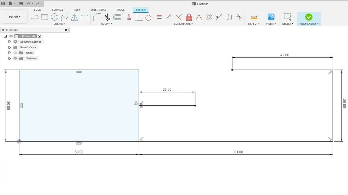
- Drag the mouse to the right to create a horizontal line of 23.5 mm. You can enter this value manually with the keyboard.
Easy, right? To practice a little, draw the three lines, with the correct dimensions, that are shown below. Start at the lower right corner of the rectangle and move your way up.
To turn the sketch into a three-dimensional solid, the 2D profile must be a closed shape, meaning that all lines and geometric shapes must form a closed loop. For instance, the rectangle we first drew is, by itself, a closed shape, as indicated by the light-blue interior color.
Let’s close this profile with a curved line using the Arc feature. First, make sure your profile looks something like the one shown above; only then should you move forward to the next steps.
Arc
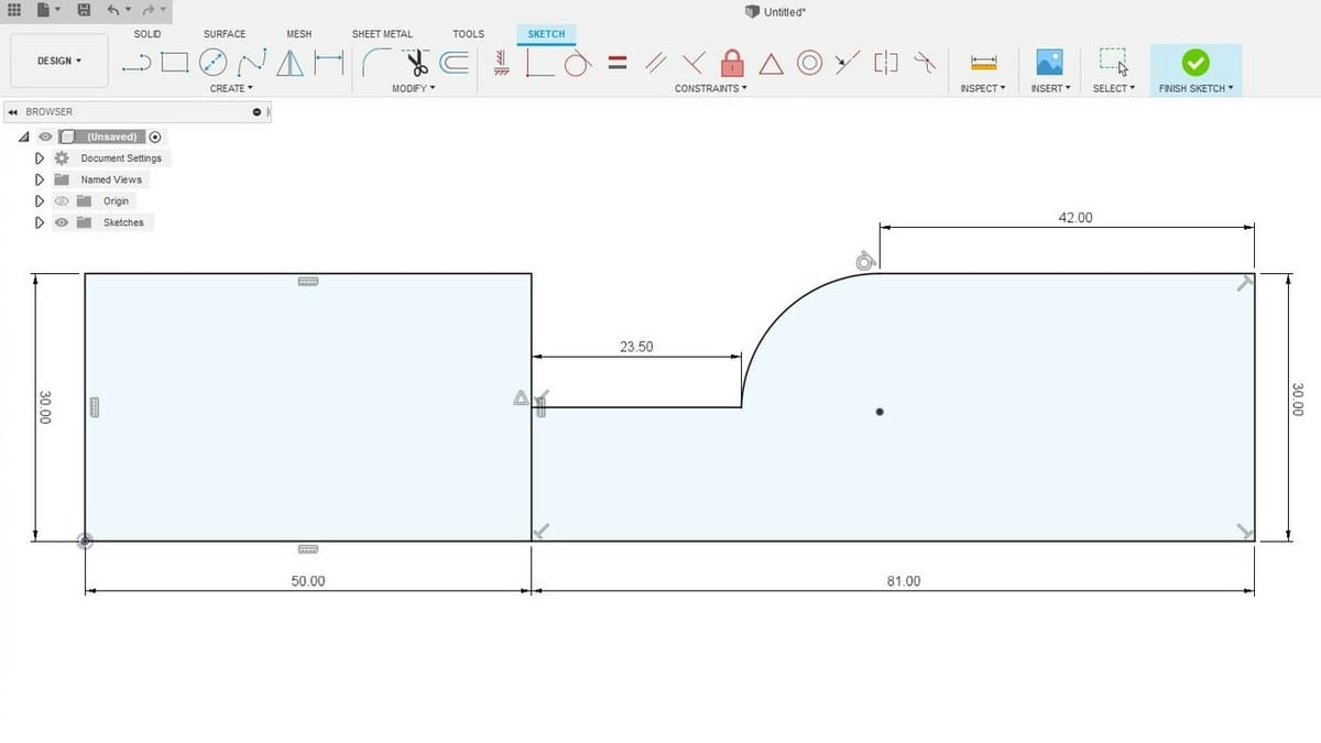
- Select the “Tangent Arc” tool. In the top toolbar, go to “CREATE > Arc > Tangent Arc”. This tool will create an arc that is, well, tangent to two other entities.
- Start by left-clicking on the open vertex of the 42-mm line and then click on the 23.5-mm line vertex. This will close the segment.
- Click on the “Finish Sketch” button located in the floating window to the right.
If all went well, you should now have the 2D sketch shown in the image below. Congratulations, this is your first finished sketch!
Part 2: Extruding
It’s time to go 3D! Extrude is perhaps the most simple and popular 3D modeling feature, found in most CAD programs.
The sketch profile we created represents the lateral surface of the vehicle’s chassis, with proportions and dimensions defined within a two-dimensional space. Let’s add a third dimension to it by setting the width of the chassis.
Extrude
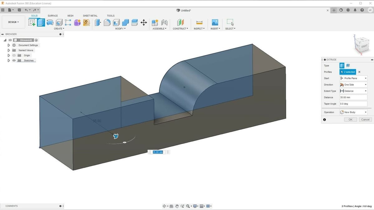
- Select the “Extrude” feature in the top toolbar.
- Hover your mouse over your sketch. Note that each closed shape will be highlighted.
- Left-click both of your shapes to select them at the same time.
- Enter a value of 35 mm for the extrusion. You can do this by orbiting around the sketch with the middle mouse button, finding a small blue arrow, and spotting the dimension window. Note that the sketch profile has turned into a 3D solid, and the direction of the extrusion followed that of the blue arrow we just mentioned.
- Click “OK” in the feature window to the right to confirm your extrusion, or simply press Enter.
And there you have it: your first solid. But we’re not done with Extrude just yet.
Right now, the chassis is rather blocky, so let’s open up some space for the back wheels of the vehicle.
To do this, we’ll create yet another sketch, but instead of creating new bodies, we’ll use the Sketch and the Extrude features to carve some details out of our 3D solid.
Sketch & Reposition
- Click on “Create Sketch” and select the side surface of the new solid. This is the 2D profile we just sketched, but we’ll create a new sketch on top of it.
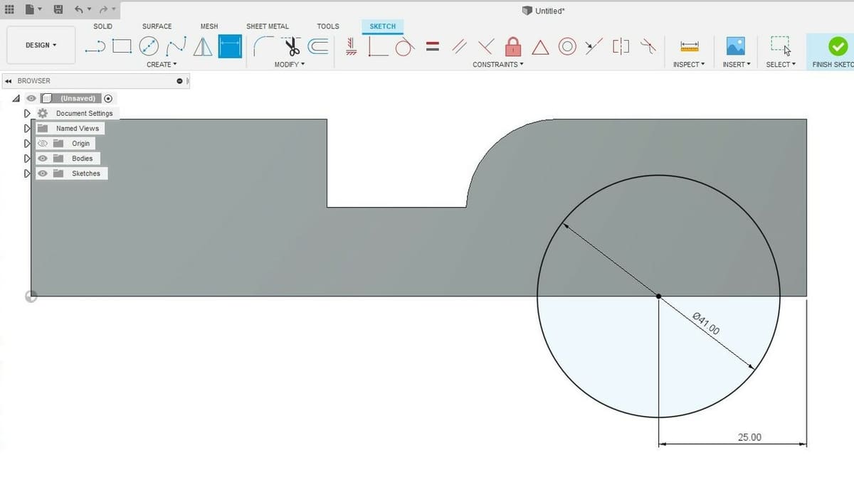
- Select the “Center Diameter Circle” tool from the top toolbar and click somewhere on the bottom horizontal line of the model. A left click will position the circle’s center, and don’t worry about the exact location; we’ll deal with that in a second. Just make sure it’s on the line.
- Enter a 41-mm diameter value for the circle and press Enter.
- Now, to properly position the circle along the line, select the “Sketch Dimension” tool in the top toolbar or press the letter ‘D’ on your keyboard.
- Click on the center of the circle and then to the lower right corner of the solid model. If done correctly, a new dimension will appear on the screen. Left-click to confirm the selection, add the dimension values of 25 mm, and hit Enter. The circle will automatically move to the new position.
Cool, right? The “Sketch Dimension” tool can be used to dimension any sketch entity as long as no numerical value has been input yet.
Now, moving on, let’s draw a profile that we can use to carve out space for the front wheels. Let’s use the Line tool once again, but this time we’ll draw them with an angle.
Line at Angle
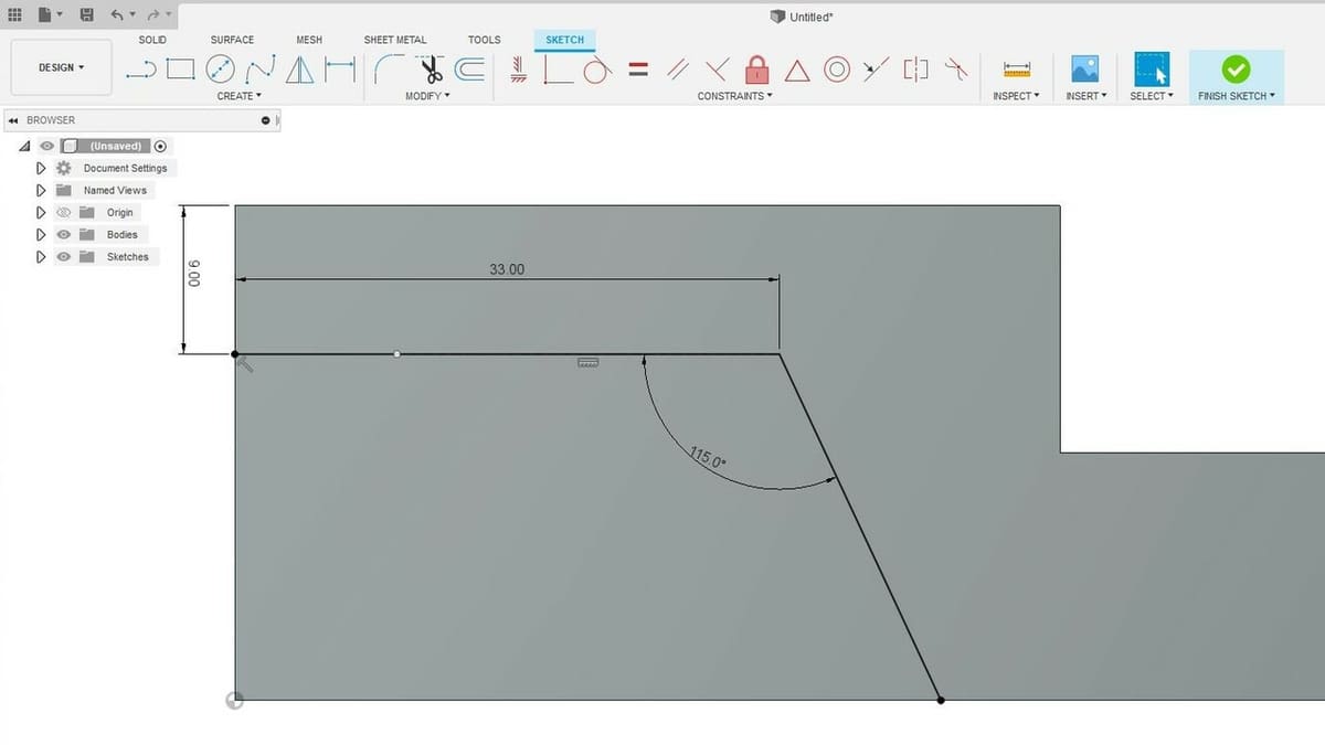
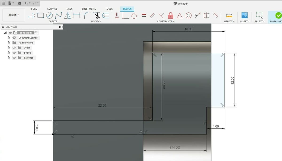
- Using the Line tool, create a horizontal line starting from the left-most edge of the solid part, as shown. Enter a 33-mm dimension.
- Add a sketch dimension between the start of this line segment and the top left corner with a value of 9 mm.
- Create a new line, this time starting at the other edge of the first segment to the bottom edge of the solid, without clicking on it yet.
- Since this line is neither horizontal nor vertical, a separate input window for the angle will appear.
- Enter the value of 115° and hit Enter.
- Make sure your new sketch looks like the one shown in the image above and click “Finish Sketch”.
Awesome! Now that we’ve defined the 2D profiles, we’ll use the Extrude feature once again to add a third dimension to them. This time, however, the input value will determine the depth of the cut we’ll perform.
Extrude to Cut
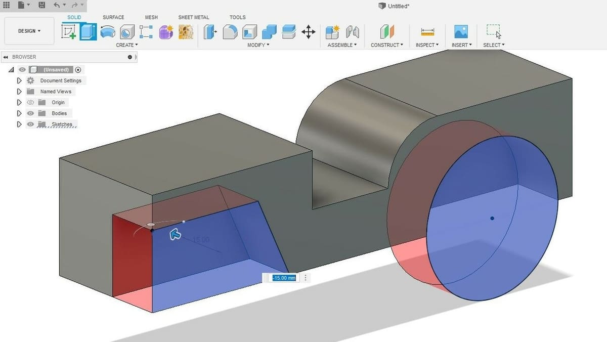
- With the “Extrude” tool active, select both the shapes we just sketched.
- To have them remove material, enter the value of -15 mm in the dimension window. The negative sign of the dimension is telling Fusion 360 that we want the extrusion to happen in the opposite direction of the blue arrow. Observe that a red region will appear when extruding towards the solid, which informs us that material is being removed at those locations.
- Press Enter to confirm the operation.
Having done this, you can imagine how many things can be created only with the Extrude feature, alternating between adding and removing material. It’s by far the most efficient method to create solids, but let’s check out yet another 3D modeling feature.
Part 3: Revolving
The “Revolve” feature is also a popular tool in CAD and 3D modeling software. Like Extrude, it requires a sketch to create a 3D solid, but it makes life easier when modeling round and symmetrical objects.
If you think about it, wheels and axes fit this description very well, so let’s experiment with the Revolve feature to create them. Let’s create a closed-profile sketch. You might be surprised by how it will look…
Sketch for Revolve
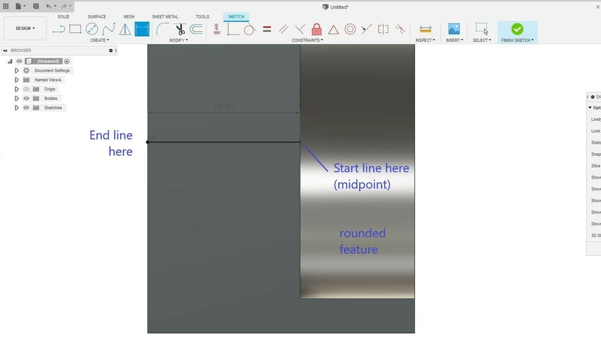
- Create a new sketch on the bottom surface of the model, and zoom into the rounded region we just extrude-cut.
- Start by creating a horizontal line starting from the midpoint of the segment as shown above to the left edge of the solid.
- From there, recreate the profile shown below using only simple lines. You should be mastering lines by now!
- Be sure to close the profile by creating a line that ends where the first one started.
- Make sure all the shapes are closed, then click on “Finish Sketch”.
Now for the fun part. The Extrude feature adds a third dimension along the axis that is perpendicular to the profile plane. The Revolve feature, on the other hand, adds or removes material by literally revolving profiles around a selected axis, also known as a centerline.
This concept might sound a bit abstract, but let’s create a 3D wheel and axis at the back of the vehicle using the Revolve feature to illustrate it.
Revolve
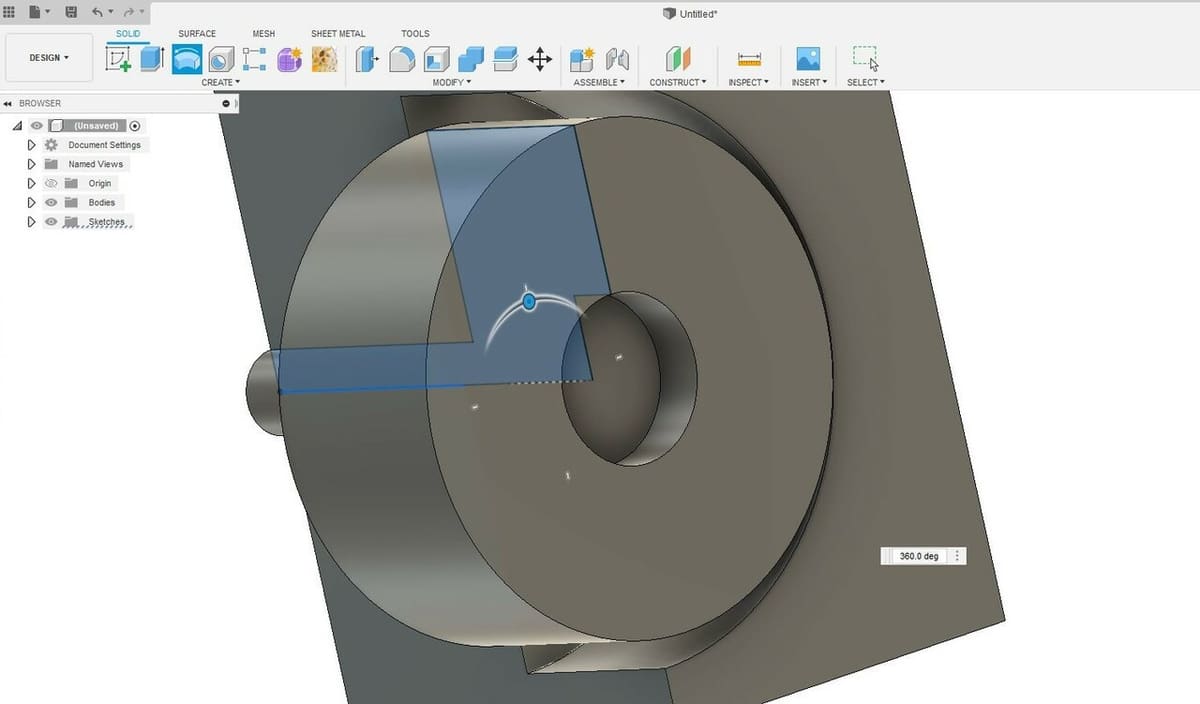
- Select the “Revolve” tool located in the top toolbar. Using this tool requires several steps.
- The first thing we need to do is assign the revolve profiles. Select the two drawn shapes from the previous sketch, just like we did with the Extrude feature.
- Then, at the feature window to the right, click on the “Select” button right next to the “Axis” setting. This will be the centerline of the Revolve operation.
- Finally, select the first horizontal line we drew in the previous sketch. If you orbit around, you’ll note that a new solid region will appear, but it is set to remove (cut) material.
- In the “Operation” setting in the feature window, select “Join” from the drop-down menu. This tells Fusion 360 to add material instead of removing it. Click “OK” to finish.
Et voilà! The first wheel is done! Our model is finally starting to look like a vehicle, and now we’re down to just a few more steps.
Part 4: Mirroring
The “Mirror” feature is a powerful tool for any 3D modeling workflow. It’s especially useful for symmetrical objects and allows us to more quickly model, as we’ll see next.
This feature quite literally mirrors a specific solid or small feature, but it requires a plane to mirror such things through. Let’s create the front wheel using this feature. To do that, we’ll have to first create the place to mirror the back wheel.
Plane for Mirror
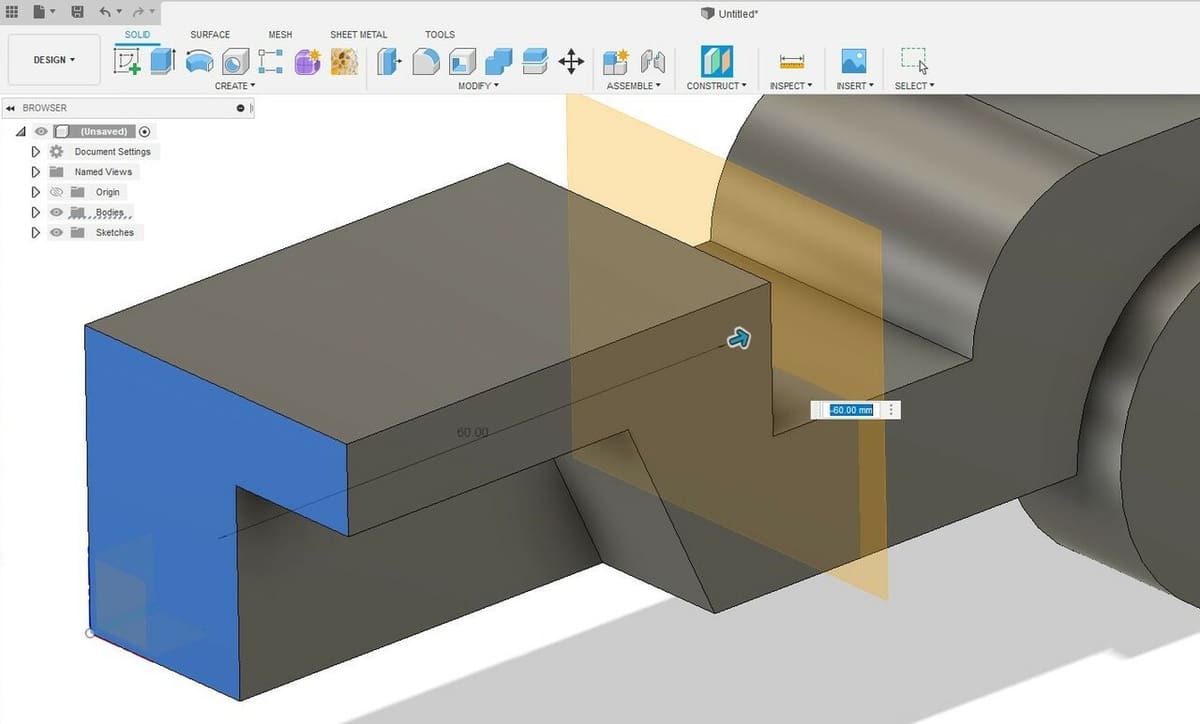
- Select the “Offset Plane” tool in the “Construct” drop-down menu in the ribbon toolbar. (Construction planes serve as references for 3D modeling tools.)
- Select the front vertical surface of the vehicle, which coincidently is also the XZ plane. (See the above image.)
- Now, you can either enter -60 mm manually or click on the blue arrow and drag it towards the model’s center until this distance is achieved.
- Click “OK” when done.
You’ve created a new plane, so all that’s left is to choose what we want to duplicate. The Mirror feature can duplicate anything from entire bodies to small features and operations, and since we want to duplicate the back wheel and axis assembly, we should select this specific feature of our model.
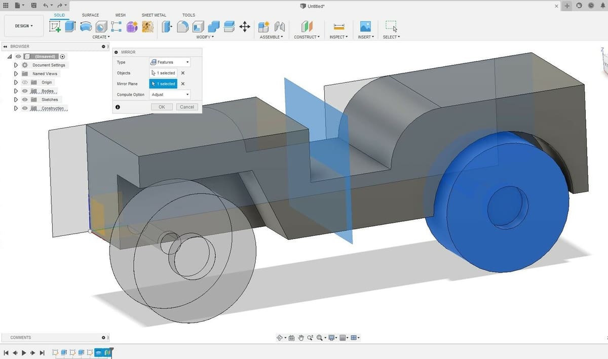
Mirror Wheel
- Select the “Mirror” feature under the “Create” drop-down menu.
- In the feature window, for the “Type” parameter, select “Features” from the drop-down menu.
- With your mouse, directly click on the wheel or click on the Revolve icon located in the Design History timeline.
- Now, click on the “Select” button next to the “Mirror Plane” setting in the feature window.
- Then, select the newly created plane on the center of the model.
- A preview of this operation will be shown, and if everything was done correctly, the front wheel should appear in the right spot.
- Click “OK” to confirm.
Great! We now have something resembling a vehicle, but only half of it. Let’s correct that by completing the missing half of the vehicle again using the Mirror feature.
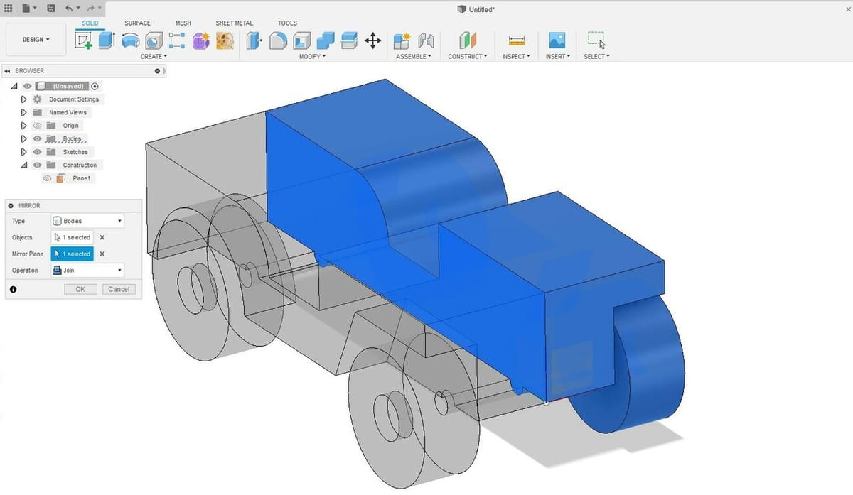
Mirror Vehicle
- Select the Mirror tool once again, but this time select “Bodies” from the drop-down menu in the “Type” setting.
- Click on the model.
- Click on the “Select” button next to the “Mirror Plane” setting in the feature window.
- This time, click on the model’s “interior” lateral surface (the one furthest from the wheels). Note that we’re not selecting a construction plane but a surface of our model.
- Click “OK” to confirm. You should now have a 4-wheel vehicle.
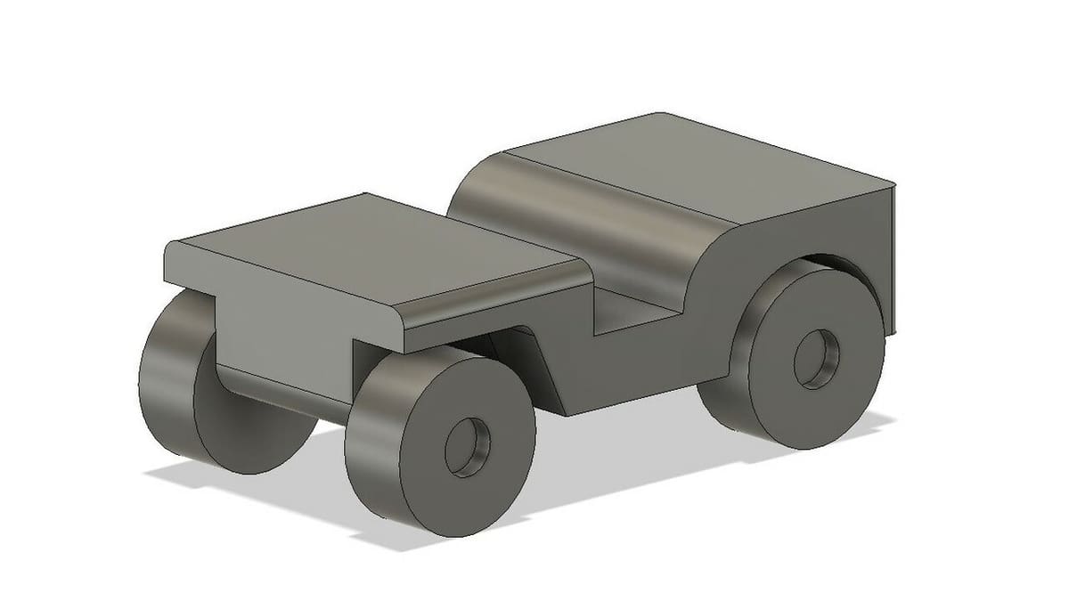
Congrats! Now it’s time to add some detail.
Part 5: Filleting
Fillet is one of the most satisfying features to use in 3D models. It creates rounded surfaces by either adding to or removing from a solid model.
Our model finally looks like a vehicle, but it still feels a bit raw. The Fillet tool will help us break sharp edges and corners and give them a more natural look. Let’s start with the hood.
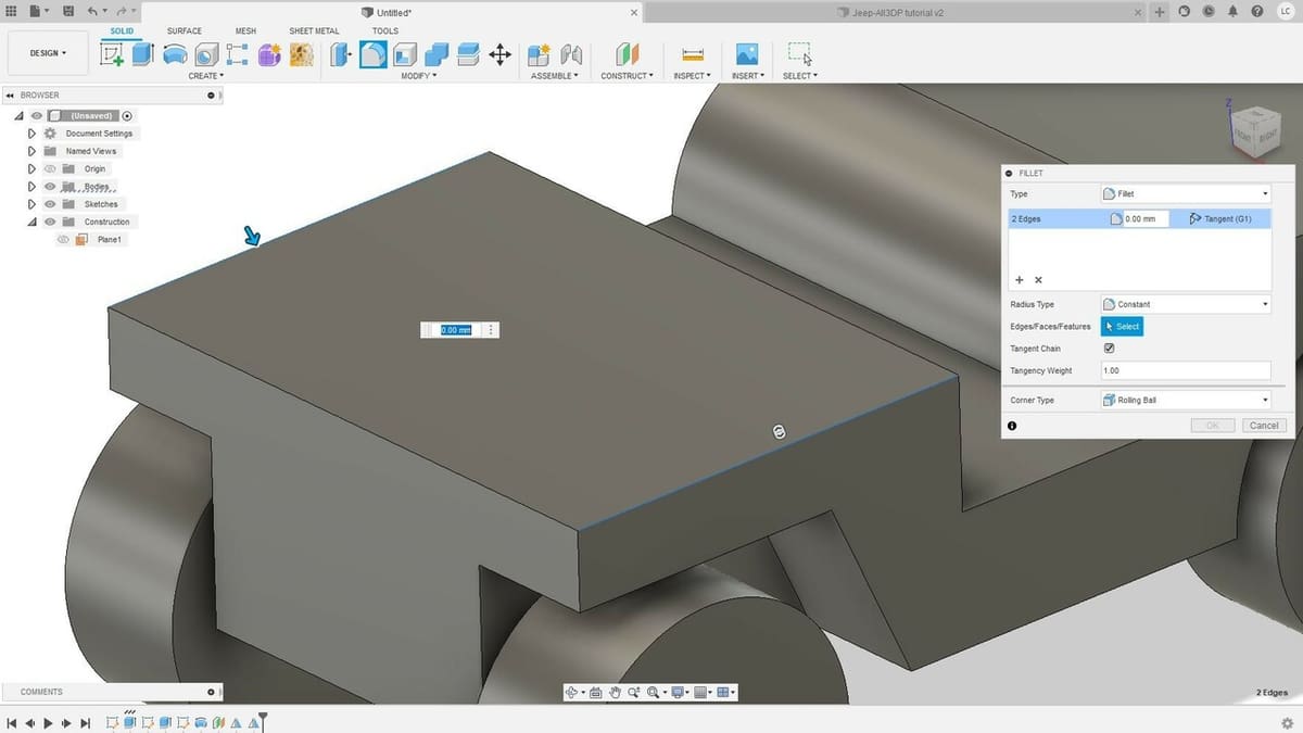
Fillet
- Select the “Fillet” tool under the “Modify” menu of the ribbon toolbar or press ‘F’ on your keyboard.
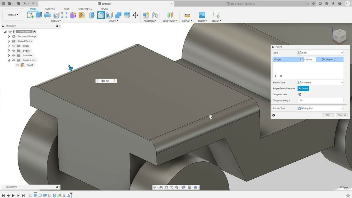
- Click on the lateral edges of the top of the hood, as shown above.
- Here you can either drag the blue arrow towards the edge to round it or enter a radius value. For this edge, we’ll go with a 4.0-mm radius, but suit yourself! After all, this is your model!
- Click “OK”.
How cool is that? Now, it’s time to take a creative leap here. Practice around with the Fillet feature, especially around the wheels, and try to make the model more to your liking!
Final Touch-Ups
Now that you’re familiar with the essential tools of Fusion 360, take some time to play around with the features we learned in this tutorial, adding more details to your model.
Here are some things you could try:
- Round all four wheels and other sharp corners with the Fillet tool.
- Open up space in the back of the vehicle by creating a rectangular sketch profile and removing material with Extrude. This will likely expose the back wheels, in which case you could make covers for them with Revolve.
- Create a front grill and lights by sketching and extruding these features from the front surface of the vehicle.
- Design a windshield frame by sketching and extruding from the lateral surface and then remove material with another sketch and extrude.
Next Steps
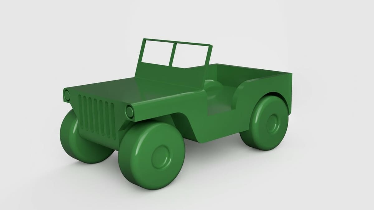
And that’s it! Congratulations on your first Fusion 360 model! Together, we created a fun little model using just a handful of tools. Imagine how many other models can be made using just these basic tools, and we barely scratched the surface!
There are a few other basic 3D modeling tools we didn’t cover here, like the “Loft” feature that automatically connects two profile surfaces and the “Pattern” feature that recreates operations and bodies to cut off tedious repeatable operations.
In the second part of this tutorial, we’ll explore some tools and techniques to make this model ready for 3D printing, so don’t miss that!
Also, be sure to check other articles and tutorials about Fusion 360. If you want to show off your creations in a polished and awesome-looking manner, 3D rendering is your best bet. If woodworking is your thing, we’ve got you covered in that as well.
And if you want to go deeper into learning this fantastic CAD tool that is Fusion 360, discover the best online courses and training available for expanding your knowledge. Until next time!
License: The text of "Fusion 360 Designing: How to Get Started Modeling" by All3DP is licensed under a Creative Commons Attribution 4.0 International License.
CERTAIN CONTENT THAT APPEARS ON THIS SITE COMES FROM AMAZON. THIS CONTENT IS PROVIDED ‘AS IS’ AND IS SUBJECT TO CHANGE OR REMOVAL AT ANY TIME.