Fusion 360 & Woodworking: How to Get Started

Fusion 360 is a versatile software for CAD, CAM, and CNC. Read on to learn about the best add-ins to optimize Fusion 360 for woodworking.
Fusion 360's Possibilities

Fusion 360 is a comprehensive tool for 3D computer-aided design (CAD), modeling, manufacturing, industrial design, and many other fields. Fusion 360 is an Autodesk product, the same company that sells AutoCAD. However, AutoCAD is a tool specifically for modeling, while Fusion 360, as the name suggests, covers the whole design process. This eliminates the rounds of exporting and importing that are needed when working with disconnected software.
There are many reasons why Fusion 360 is particularly suited to woodworking applications. First, it has all the necessary tools to move from designing to manufacturing in one place. Additionally, the software is aesthetic and intuitive, you can preview the cutting process beforehand, and it has a database of existing standardized mills, so it’s easy even for beginners to figure out. Fusion 360 also has the added bonus of being free for hobbyists and students, although there’s also an even-more-powerful version for commercial use.
In this article, we’ll be highlighting some add-ins for Fusion 360 that’ll help you set up a part for woodwork. We’ll assume a basic knowledge of modeling, whether in Fusion 360 or elsewhere, or that you already have the model you plan to use. We’ll first go over some basic concepts that are important to understand when working with CNC, then take a look at six add-ins that will perfect your woodworking workflow.
Using CAM
Before we jump into the add-ins, let’s review some basic concepts that are important to know when working with CNC.
Cutting Strategies
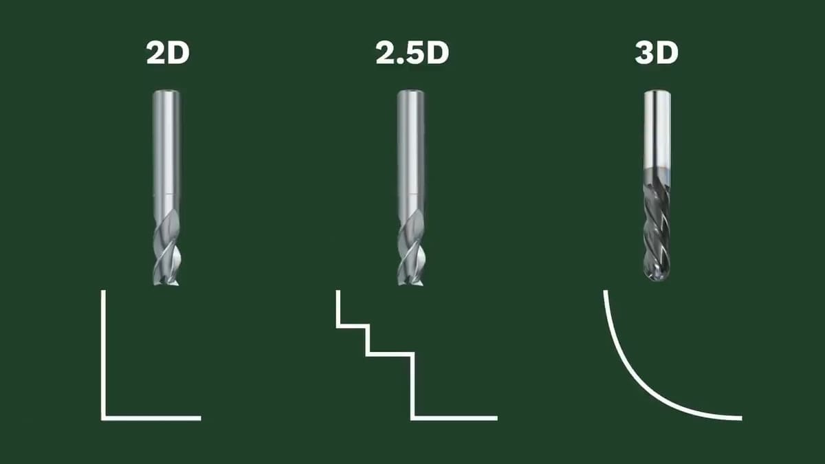
CNC projects use one of three cutting strategies: 2D, 2.5D, or 3D cuts.
- 2D cutting refers to when the tool cuts a shape at a single height, such as laser cutting.
- 2.5D cutting means the machine still traces a 2D shape, but it’s able to stop and vary the height (just not at the same time as XY movement).
- 3D cutting is when a machine can move through all three axes at the same time.
CAM
Computer-aided manufacturing (CAM) is the process of setting up the material, tool, and toolpath, and then exporting G-code to instruct the machine. This process only occurs after CAD, when the model to be cut is final.
- Defining the material mainly consists of defining the dimensions of the slab of wood to be cut. Things such as the material are the maker’s choice and doesn’t affect the program.
- Choosing the tool refers to the cutting tool that’ll be used. The main thing to remember is that the diameter of the mill should always be smaller than the shape you intend to cut. In this step, you should also define speed and feed. The speed refers to how fast the mill rotates, and the feed to how fast it translates per revolution.
- Setting the toolpath is where you tell the software which shapes to cut out and which shapes to keep. This is pretty easy in Fusion 360, you just have to click the shapes you want to cut and then generate the G-code, with an option to first preview the cutting process. On that note, it isn’t necessary to be able to write the G-code yourself as the program will do that for you, but you should be able to somewhat understand it, in case you need to tweak some things manually.
Add-ins
Fusion 360 allows third-party developers to create plug-ins that extend the software’s functionality. These are called add-ins and are available in the Autodesk app store.
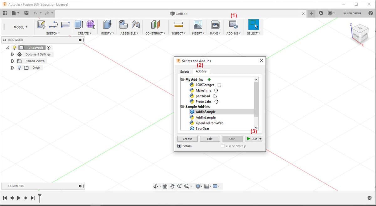
To install an add-in, you simply head to the Autodesk app store, download the desired add-in, run the installer, and then open Fusion 360. When in Fusion 360, click on “Scripts and Add-Ins” (see above image: 1), go to the “Add-Ins” tab (2), select the desired add-in, and click on “Run” (3). (If you’re running an older version of Fusion 360, it may be necessary to go to the “Tools” tab, before finding the option for “Scripts and Add-Ins”.) Finally, restart the program and the add-in will appear in the “Create” section.
If an update is available, a button for the update will appear to the right of the add-in. Simply click on this button, wait for it to update, and then restart the program.
So now we know how to properly install them, let’s look at the add-ins!
OpenBOM
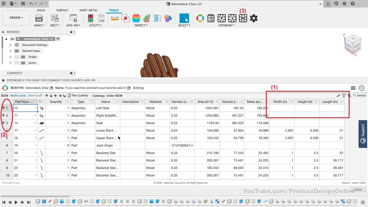
BOM stands for Bill of Materials, which refers to the list of all the materials used in an assembly. Open BOM allows the user to create a list of materials, and even adds automated measurements.
Out of many BOMs available in the app store, this freemium add-in is by far the most complete, with two stand-out features. The first is its ability to automate dimensions of height, length, and width for each piece (see image above: 1), which saves time when getting the material you’ll need for your CNC. The second main advantage is that it allows multi-level BOMs, which means that it can include sub-assemblies or nested components on the list (2).
How to Use It
To generate the list, simply click on “Create multi-level BOM” (3), in the Tools tab. If the model is changed in any way, click that same button again and the list will update. Moreover, the generated BOM can be opened via a web browser, or saved as a PDF or Excel spreadsheet.
Mortise and Tenon
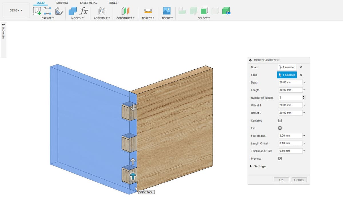
Mortise and Tenon, as the name suggests, creates automated mortises and tenons for easier assembly.
This add-in saves you the time for something you otherwise would have to do manually, which is creating joints. You can specify the dimensions and location of the joint, so it’s particularly useful in woodworking.
How to Use It
Simply select the two pieces you want to join, and the program will recognize the points in contact, creating the mortise and tenon joint between the two surfaces. You can set the number of joints and choose whether they should be equidistant or have a particular distance between the tenons. It can be applied not only on the edges of a part but also in the middle of the part.
Dowel Joint
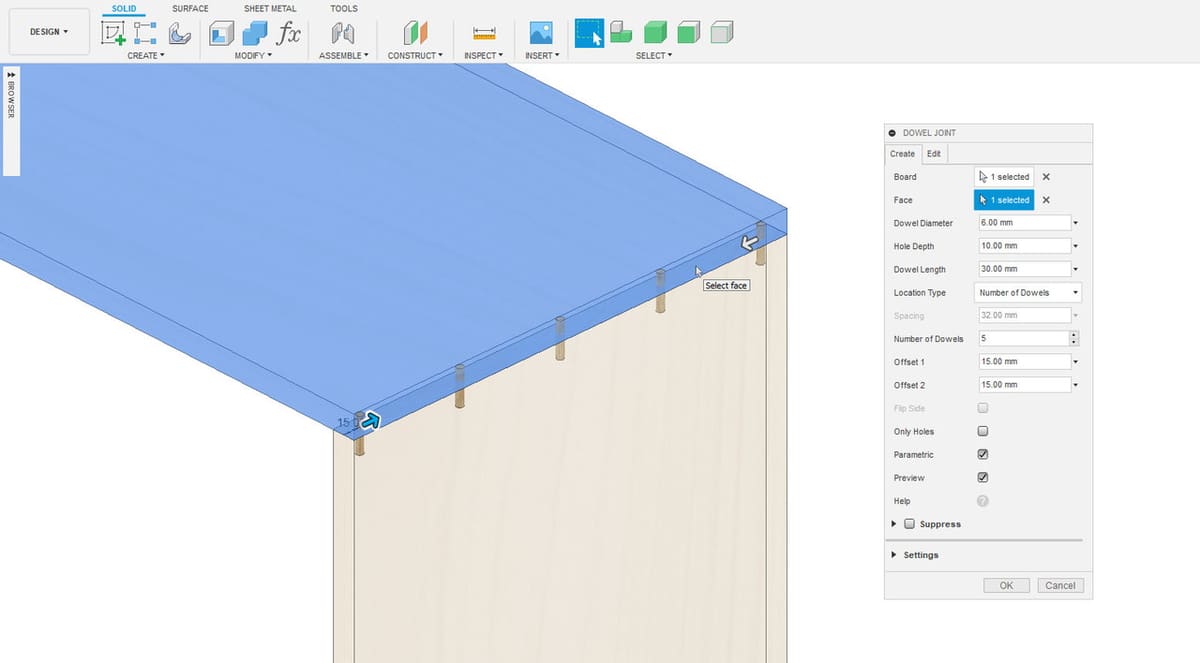
Like the previous add-in, Dowel Joint allows you to create automated joints, but in this case, dowel joints, which are useful when a part’s body has to sustain greater loads.
Similar to Mortise and Tenon, this add-in saves you the time you would otherwise spend manually setting up dowel joints. Dowel joints are used when you need the connection between two components to be sturdy enough to support a force.
The mortise and tenon method creates a connection geometrically, but it’s actually only able to support loads that go inwards in relation to the part, meaning it can’t support flexion or tension forces, so it’s mostly used for toys. Another option to solve this issue is using glue, but even then, glue can only support shear stress.
Though dowel joins are used when you need stability and resistance, they’re only recommended for bigger parts. If employed in small parts, the hasp would have the diameter of a toothpick, so it would break too easily, defeating its purpose.
How to Use It
To use the add-in, you simply select the two pieces you want to join, and the add-in recognizes the points in contact and generates the joint. You can also customize the dowel diameter, hole depth, and set whether you want equidistant spacing. However, it’s not possible to have dowel joints in the middle of a piece, only on the edges.
DXF for Laser
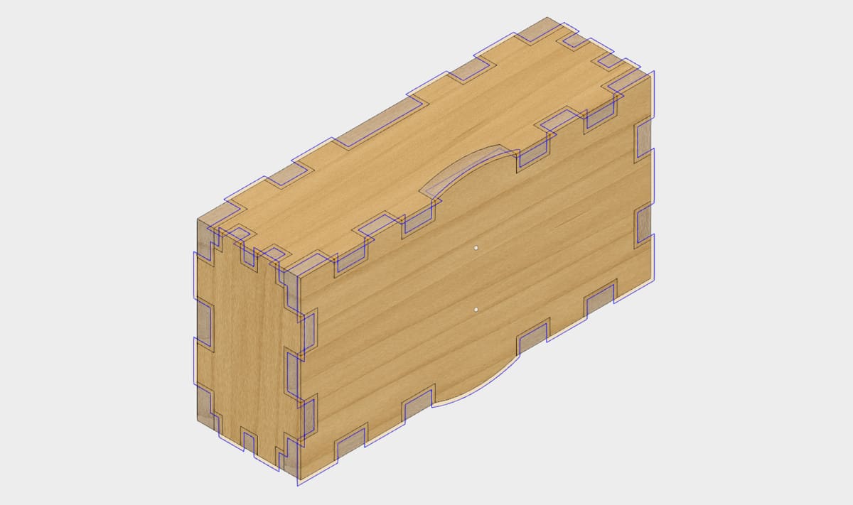
DXF for Laser adjusts the geometry for the width of the laser cut so you have full control over how tightly your parts fit together.
This add-in may seem like overkill but it plays a vital role, as the tolerance of your part is an important consideration. Tolerance refers to how loosely or how tightly two parts fit together. For example, for a clock, you’d need some parts to slide over others and some to be a close fit, to ensure that the time is counted correctly. This add-in takes into account the width of the cut left by the laser to ensure your final part will have the exact measurements you need.
How to Use It
According to Esabna, “a cutting kerf is defined as the width of material that is removed by a cutting process. When talking about CNC shape cutting with typical cutting processes, the kerf is the width of material that the process removes as it cuts through the plate”.
By using this add-in with a small, or even negative value for your kerf you can make loose-fitting parts, which are useful for a child’s puzzle, perhaps. In contrast, by using a positive value, or a value larger than the actual kerf you calculated, you can make parts that need to be gently tapped into place for no-glue assembly. Meanwhile, a kerf of 0 will simply generate a clean DXF file without any offsetting of lines.
Voronoi Sketch Generator
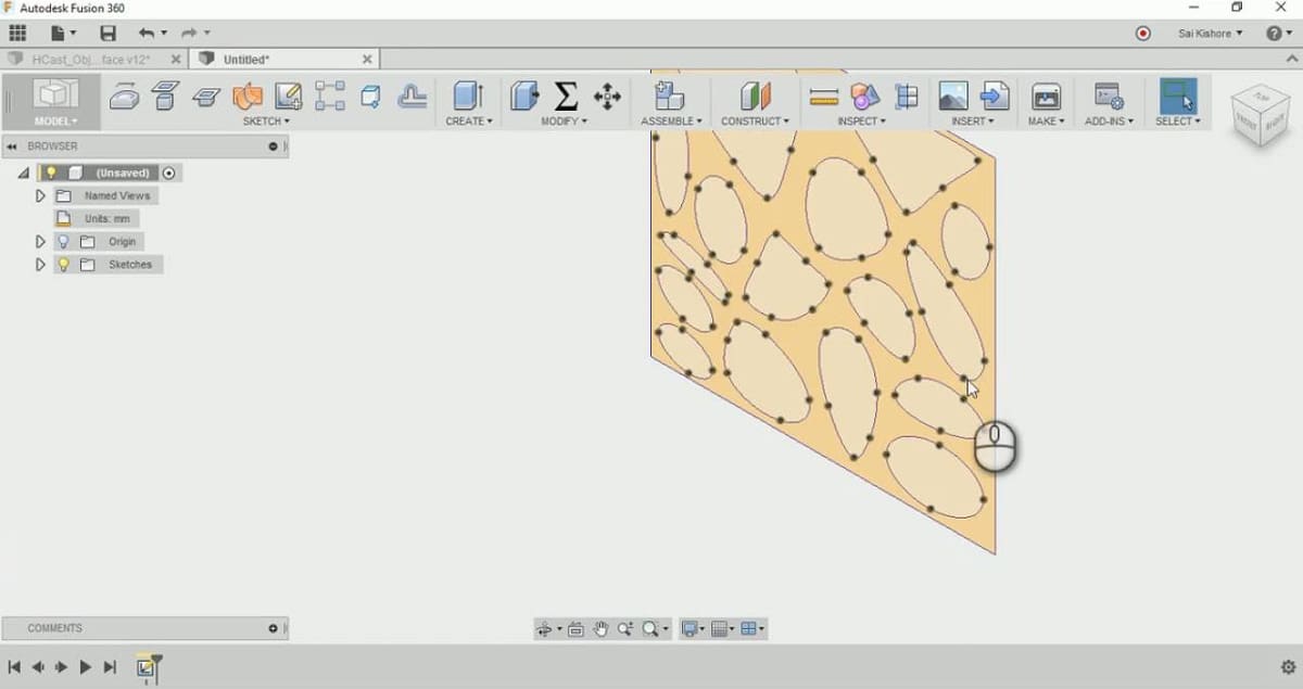
Voronoi Sketch allows the user to create the popular Voronoi style that’s largely used for CNC-made decorations.
In mathematics, a Voronoi diagram is a “partition of a plane into regions close to each of a given set of objects. In the simplest case, these objects are just finitely many points in the plane (called seeds, sites, or generators)”. In manufacturing, Voronoi sketches are very popular patterns used in CNC for wall decorations and other household items. The style results in surfaces full of organic-looking holes.
How to Use It
This add-in allows you to generate Voronoi sketches by setting various parameters that’ll affect the generated forms. It doesn’t create the surface, just the sketch; you would have to extrude it or cut it into an existing part.
This is a simple add-in, but aesthetics-wise, it’s very useful to quickly and easily enhance a model. However, it’s important to take into account that this add-in is only available for macOS.
Spur Gear Creator
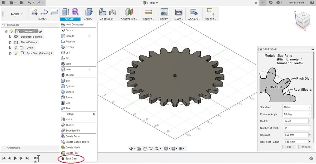
Spur Gear Creator is actually a default add-in available when you install Fusion 360, you just need to hit “Run”. It allows the user to create gears using standardized measurements.
Gears are regulated by norms and equations that determine their dimensions, according to certain parameters like the number of teeth and nominal diameter. As an experienced designer, you should never waste time hand-drawing the teeth of a gear from scratch, as this is difficult, time-consuming, and most likely you won’t get it right. The only case when it would be worthwhile to be drawing the gear from scratch is when you’re just learning gear theory.
Many users aren’t aware of this pre-installed add-in, so they don’t run it or end up installing new, less complete alternatives. On that note, we recommend checking out the other default add-ins that come pre-installed with Fusion 360. You might find just what you’ve been looking for!
How to Use It
With that in mind, any competent modeling software should have a toolbox available where you can access standardized parts and adjust the aforementioned parameters. Then, the desired part will be automatically generated with the appropriate dimensions. That’s the function of this add-in, specifically for spur gears, as they are the ones that can be achieved for CNC (conic or helicoidal teeth can’t be manufacture with CNC milling).
Lead image source: CIMx Software
License: The text of "Fusion 360 & Woodworking: How to Get Started" by All3DP is licensed under a Creative Commons Attribution 4.0 International License.