How to Design Parts for SLA 3D Printing

Learn how to optimize your designs for SLA 3D printing, a not-so-simple 3D printing technology. In this guide, we present a number of tips that'll take you down the road to success!
Practical SLA Design

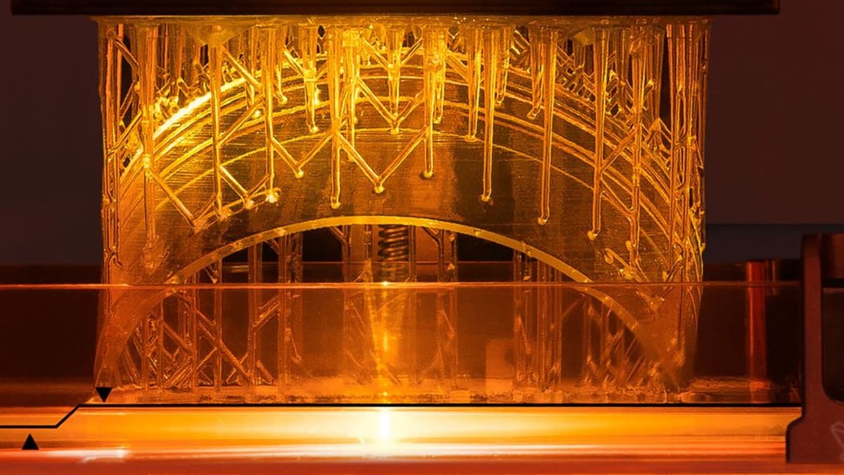
Stereolithography (SLA) uses a laser to very accurately cure photopolymer resin, allowing designers to create complex, detail-rich models. Like all other 3D printing processes, SLA begins with a three-dimensional model, which is a digital representation of the three-dimensional object to be printed.
An SLA model will typically be created using computer-aided design (CAD) software before being exported as an STL or OBJ file to be prepared for 3D printing. One of the requirements for a good print is a well-designed model that is optimized for 3D printing.
While there is no extensive or ultimate guide for SLA designing, there are conventional techniques and proven methodologies that will give you a practical SLA design. In this article, we want to explore these techniques and methods.
Since SLA printers have different specs and capabilities, we will be using standard figures from industry experts, including reputable printer manufacturers and 3D printing service providers. As a designer, expect using slight deviations from these figures.
Hollowing

Printing a solid, dense part increases the amount of material needed, which increases the cost, and should only be considered if the piece is functional. This is why hollowing is a common practice in SLA; it saves on material and time.
Unfortunately, unless dealt with, hollowing will lead to uncured resin being trapped inside your final print.
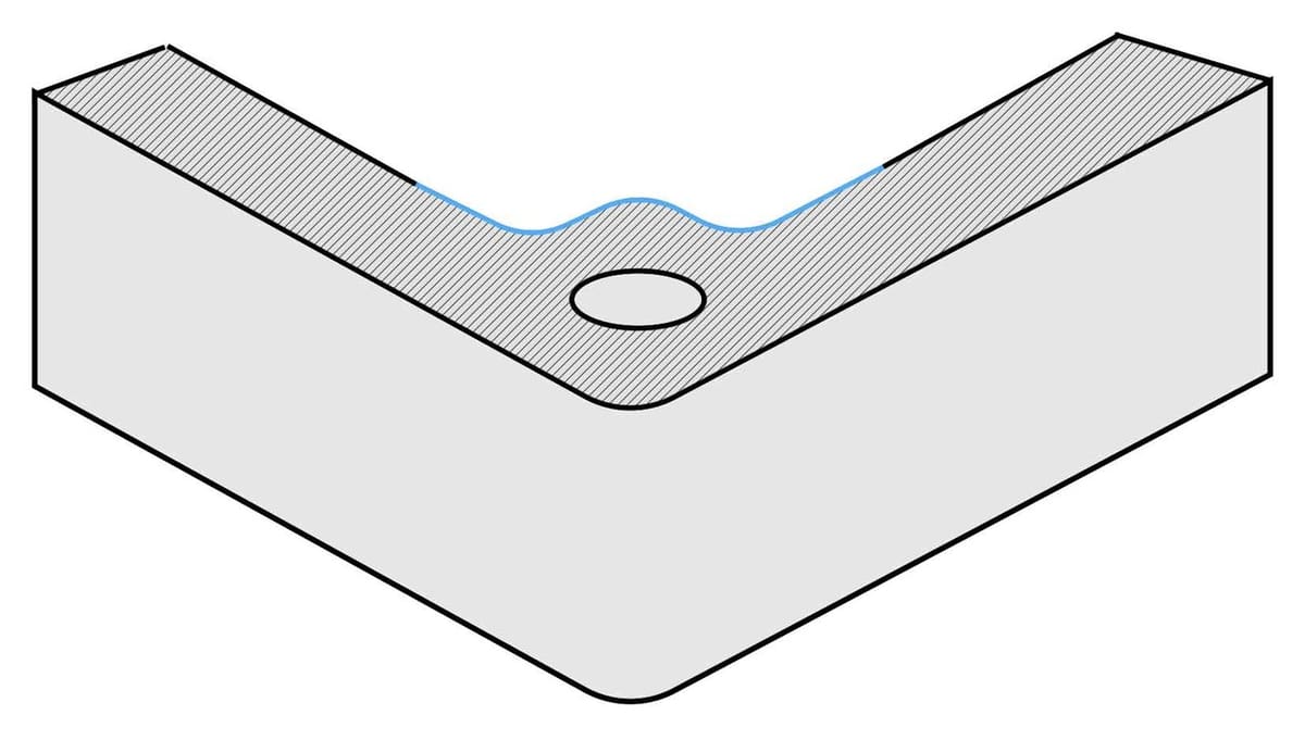
Solution: Add drainage holes to your model.
Drainage holes are usually placed at the lowest point of your piece. In addition to acting as outlets for excess resin, holes ensure that the pressure of the liquid is equal on either side of the model’s walls. The location of your drainage holes is up to you but will usually depend on the orientation of the print.
According to Formlabs, the recommended diameter for a drain hole is 3.5 mm. Otherwise, the part will trap resin, which may lead to an explosion.
Walls

Walls present several challenges, many of which can be easily addressed at the design stage:
First, thick walls will tend to use more resin, and this increases the cost of printing.
Second, if walls are non-uniform, the thin sections, which have less material, will tend to shrink less and will stop shrinking sooner than the thicker parts with more material. This will eventually lead to warping and cracking.
Lastly, unsupported walls are likely to detach or warp.
Solution #1: Keep walls thin.
With thinner walls, the object will weigh less, and you will use less resin for the part, which is more cost-effective. This is especially important for bottom-up SLA 3D printing, where the printed part hangs upside-down and is subjected to gravitational force. The Envisiontec Vida and the Formlabs Form 2 are examples of bottom-up SLA printers.
Just make sure that your walls are not too thin, as this makes the printed part more fragile.
The only exceptions to this rule are unsupported walls. These walls are connected to the rest of the printed part on less than two sides and are therefore likely to detach or warp. 3D Hubs recommends a thickness of at least 0.6 mm for these kinds of walls and filleted bases to reduce stress concentrations along the joint.
Solution #2: Keep walls uniform.
In order to avoid cracks and warping, keep wall thickness as uniform and consistent as possible.
If it is impossible to have a uniform wall because of a design constraint, ensure that the change of wall thickness is as uniform as possible.
Overhangs

In SLA, overhangs become a concern when the model lacks enough support structures. In fact, without enough supporting structures, overhangs are impossible to print unless certain requirements are met.
Solution #1: Support overhangs of less than 19 degrees.
If by any chance you need to print without supports, any unsupported overhangs need to be at least 19° from the horizontal, according to Formlabs. Printing at less than 19° will cause the overhang to break off during the peeling process.
The peeling process occurs each time the cured resin is detached from the resin tank. This happens as the result of the build platform moving away from the light source between layers.
Solution #2: Support overhangs longer than 1 mm.
Formlabs recommends a maximum unsupported overhang length of 1.0 mm. Anything beyond this will be slightly deformed, and the deformation will increase as the length increases.
Corners

Sharp corners increase stress concentration, which can lead to cracks or a failed print.
Solution: Round corners.
In a two-dimensional context, rounding a corner is essentially replacing it with a quarter of a circle. For a corner on a block, this will produce a curve with a single radius. For a corner between two walls, this will produce two different curves with two different radii.
AmeraLabs recommends that the internal radius of a corner between two walls be 0.5 times the thickness of the wall, whereas the external radius be 1.5 times the thickness. Naturally, a bigger radius is always better, as long as your SLA design can allow it.

Small Holes

Smaller holes (with a diameter of less than 0.635 mm) are always tricky to print because they will likely close off during printing.
Solution #1: Adhere to a minimum diameter.
Formlabs recommends a minimum hole diameter of 0.5 mm, maintaining that anything less than 0.5 mm in the X, Y, and Z axes may close during printing.
Solution #2: Make holes manually.
Instead of incorporating a hole in your design, you may consider making the hole manually using a drill bit. This will save you from the frustration of an improperly printed hole.
Internal Threads

SLA printed parts suffer from resolution tolerances and tend to be fragile. As such, SLA printed threads will have little to no pull-out strength, which means the threaded part can take very little force before it gives in. Therefore, pulling out a fastener is easy.
Solution: Use threaded inserts instead of internal threads.
Since printing threads in SLA can be hectic, avoid designing internal threads and instead use threaded inserts.
Embossed and Debossed Details

For your text or fine details to be visible – whether debossed or embossed – you must meet a minimum height and width. Designing with measurements that are below the minimums will make the part unprintable, and this is a common issue when you want very small details.
Solution: Adhere to certain mininum values.
Formlabs recommends a thickness and height of 0.1 mm for any embossed detail. Anything less will not be visible. Here, thickness refers to, for example, the thickness of lines in letters, whereas height is the distance from the background surface.
For debossed details, including text, Formlabs recommends a thickness and height of 0.4 mm. Otherwise, the debossed detail is at risk of fusing with the rest of the model during the printing process.
Materialise, on the other hand, recommends a depth of 0.5 mm and a 0.5-mm line thickness for both debossed or embossed text.
Bosses
Bosses are used for attaching fasteners like screws. They are delicate parts to print because SLA parts tend to be brittle and are prone to cracks. The probability that a boss will crack or break increases when it needs tapping, which is the creation of a threaded hole on a part.
Solution: Print test parts first.
It is advisable to print test parts to determine how they work before attempting to print the entire design. Test parts are meant to test the structural strength of your design before you decide to print the final design.
Ribs and Gussets
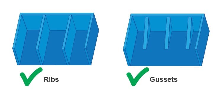
To reduce the risk of potential cracks and other stresses after 3D printing, parts are sometimes designed with ribs and gussets. Ribs are like thin walls that join features, enhancing the bending stiffness of a 3D printed part without having to make the part thicker. Gussets are a subset of ribs, where a feature is simply rooted to its base.
These two features will generally reduce the need for extra support structures, but will add more detail to your design, and, therefore, need to be designed with some specifications.
Solution #1: Keep ribs thinner than walls.
To minimize the risk of cracks, the thickness of a rib should be less than the wall it is supporting. AmeraLabs suggests setting rib thickness to 60% of the wall thickness.
If the ribs intersect, hollow the intersection to preserve uniform wall thickness.
Solution #2: Keep gussets shorter than bosses.
If a gusset is attached to a boss, it should be shorter. AmeraLabs recommends a maximum of 95% the height of the boss.
Clearance

Interlocking parts will either have too much space or very little space between them if you overestimate or underestimate the clearance. (Clearance is the distance between two moving surfaces, like gears.) In the end, the relevant parts will not move as expected.
Solution: Don’t overestimate or underestimate clearance in your design.
Formlabs recommends a minimum clearance of 0.5 mm between any two moving parts of a model. Anything below 0.5 mm may cause the parts to fuse.
That said, the clearance between two parts will often vary. 3D hubs recommends 0.5 mm between moving parts, 0.1 mm if you want a snug fit, and 0.2 mm for assembly connections.
Bridges
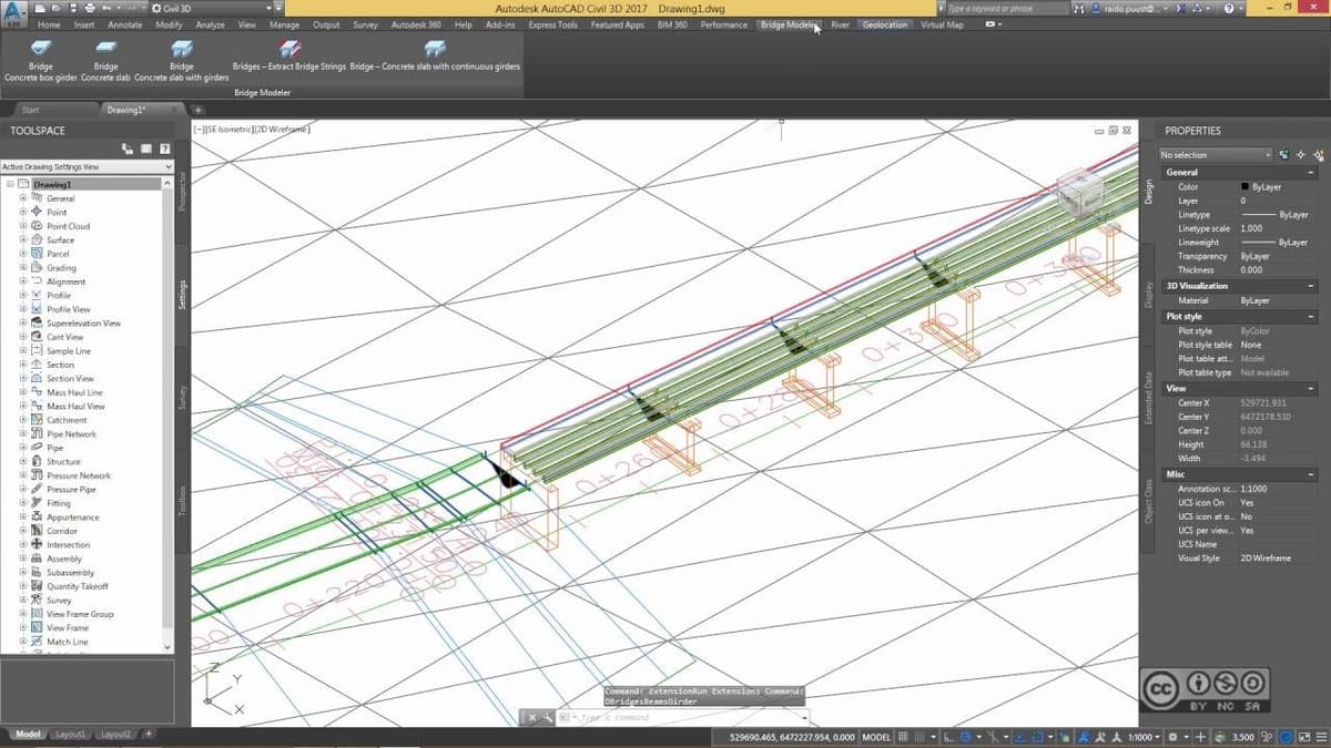
Wide bridges are problematic to print because of the larger z-axis contact, which increases the chances of the print failing during the peeling process.
Z-axis contact is simply the part of the already cured print that is in contact with the bottom of the tank, i.e. the “top” of the print. The bigger the 2D cross-sectional area of the print, the higher the forces that may cause a print to stick to the tank.
Solution #1: Reduce the cross-sectional area along the z-axis.
If you want a successful print, reduce the cross-sectional area along the z-axis. If you want to print a wider bridge, for example, you will need to keep it short compared to a thin bridge.
Solution #2: Adhere to a maximum bridge length.
Formlabs sets the maximum length of a horizontal bridge at 21 mm if the bridge is 5 mm wide and 3 mm thick. Naturally, these measurements may change depending on the printer.
Vertical Wires

A wire is a feature whose length is more than twice its width. Printing a vertical wire becomes more difficult as the wire gets thinner because the thinner the wire gets, the more vulnerable it is to defects.
Solution: Adhere to minimum proportions.
Formlabs recommends a height of 7 mm for a thickness of 0.3 mm and a height of 30 mm for a thickness of 1.5 mm.
Print Orientation

When considering orientation, the main concern (according to 3D Hubs) is the Z-axis cross-sectional area. The print is likely to stick to the tank if the 2D cross-sectional area is larger. This is because the forces responsible for the sticking are directly proportional to the 2D cross-sectional area of your print.
Solution: Minimize the cross-sectional area along the Z-axis.
You will have to orient your print at an angle if you want to reduce the Z-axis cross-sectional area, but this will increase the support structures needed.
Print Volume

On average, SLA printers have a considerably smaller build volume than FDM printers. The Formlabs Form 2, for example, has a build volume of 145 x 145 x 175 mm. This is way smaller than a standard FDM printer, like the Prusa i3 MK3, which has a build volume of 250 x 210 x 210 mm.
This definitely restricts the average size of a print you can make with SLA.
Solution #1: Design small.
If size is not crucial, consider scaling down your model. Just remember to keep all of the above factors in mind when you do.
Solution #2: Split parts.
Don’t design a part that is too big for the build volume of your printer. If the geometries are beyond your printer’s capacity, consider splitting it into smaller sections to be assembled later.
Feature image source: Formlabs