How to Split an STL File / 3D Model for 3D Printing

3D printing large parts can be a challenge! Read on to learn how to split STL files into parts using common software tools.
There are a lot of reasons why you may want to split a model into smaller parts. Perhaps your STL file is larger than your build plate. Maybe you want to print in different colors, but you don’t have a multicolor printer and you don’t want to insert pause commands at specific heights in the slicer software. Or you may want to split the model in order to lay parts of the model that would be overhangs flat on the bed in order to avoid using supports.
Sometimes, designers will make it easy for you and provide the model in pre-split pieces. When that isn’t the case, though, you can just split it yourself.
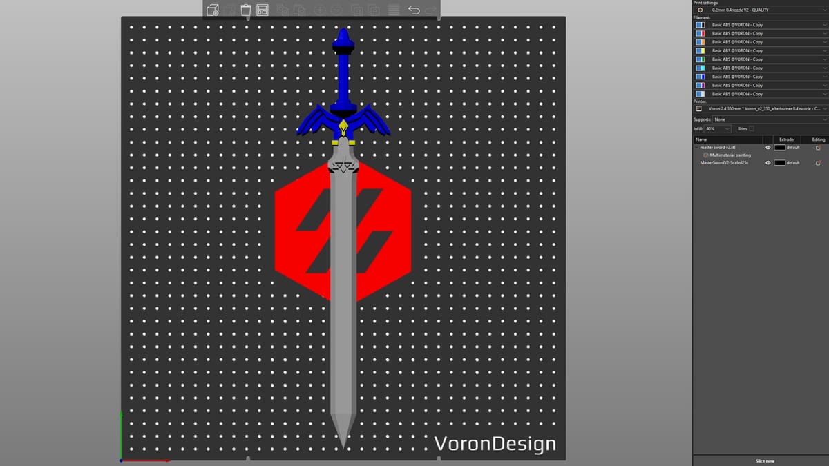
In this article, we’ll guide you through the process of splitting a model in two solid programs: Meshmixer and Blender. We’ll demonstrate the process with a model designed by Printables user (Amish)Chris: a lovely Master Sword inspired by The Legend of Zelda: Breath of The Wild. Along the way, we’ll also share some tips on how to assemble your print so you have the best shot of nailing it on your first try.
Let’s dive in!

Which Program to Use?
There are many options available for splitting models – Cura or Tinkercad, for example. To demonstrate the range of complexity, we’ll use Meshmixer (one of the easiest options) and Blender (one of the more complex options) to split models. Before we dive into the steps to split your model, we discuss both of these programs in a little more depth, and later, we’ll present a few alternatives you might want to consider as well.
Meshmixer
Meshmixer is one of the easiest and fastest ways to split your STL files. While it’s excellent for what it was made for, it can seem to be a one-trick pony when compared to some other programs. For instance, Blender can create and edit mesh models as well as be used for animation, while Fusion is known for its CAD features and now has support for editing mesh models.
While it was previously announced that Meshmixer would no longer be supported by Autodesk, the download page shows an update in November 2024. As the last release, we anticipate that there won’t be any new features or security updates. This may cause some people to switch to Fusion, which is also from Autodesk, to keep up with newer features that may come out in the future. But until that day comes, Meshmixer is still one of the frequently used programs for splitting models.
If you’re a Mac user, you won’t be able to use this program without using a Mac program called Parallels, which is software that provides hardware virtualization. You’ll want to make sure that your virtual machine has enough resources to allocate at least the minimum requirements for Meshmixer.
Blender
Blender has risen in popularity over the years for being one of the more polished open-source 3D modeling programs available. It has made it easy for anyone to be able to access the tools needed for creating stunning scenes and life-like models.
It’s not all sunshine and rainbows, though. One downside to Blender is that it can seem intimidating to first-time users, and there’s quite a learning curve to use most of what Blender offers. To help with that learning curve, you can find tutorials for beginners. In our case, we’ll be using it to split your STL files – something it does quite well!
Blender is free, and a lot of people already use it. You just need to learn a couple of tools or settings, and you can start splitting your STL right away. And the best thing is that you’re not limited to splitting the whole model into horizontal or vertical angles, as you’re able to add planes, size them, and easily angle them in any direction.
Now that you know a little bit more about the tools, let’s get to splitting.
Part I: Find the Best Cutting Points
You have a model and you’re ready to split it, but you’re not sure where to make the first cut. We’ve been there before, so here are some strategies on where to cut your model as well as other considerations to keep in mind.
If you’re printing something with high detail, you may want to think about a couple of things first. Try to avoid cuts that go directly through those detailed areas. You also may want to try splitting your model in a way that would cause the least amount of supports (i.e. split the part at overhangs so they can be printed flat on the bed instead of bridging extrusions printed in mid air).
Another thing to consider is the model’s structural integrity. This can be quite important depending on the intended use – a functional part, for instance. You may want to avoid splitting at the weakest points in a design, namely those areas that are much thinner than the rest of the model. They may not be the best place to cut, so try and stick to places with a decent amount of surface area. The more area you have to work with when assembling, the better.
If you’re a fan of Tetris, you may enjoy the next tip for finding your cutting points. Think about how you can split the model to be able to fit the most on your build plate at once. You would be amazed by how splitting a model properly can sometimes save you hours of printing time.
The next steps are program specific, so we’ll demonstrate them first in Meshmixer, then in Blender.
Meshmixer
Part II: Split the Model with Meshmixer
Meshmixer is easy for beginners to start with as the process is really straightforward and requires only a couple of steps to get the desired results.
Step 1: Import
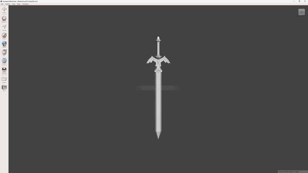
Import your mesh file by clicking on the Import plus-sign button at the top of the left-side toolbar or on the Quick Start menu. Meshmixer supports all the most common mesh file types, including STL, 3MF, and OBJ. You can also import some of the more esoteric mesh file types, so no matter what you use, you’ll probably be covered.
Tip
You may have issues with the model’s scale when you first import it. The model may appear incredibly large or incredibly small, depending on the mismatch. This can make the auto aligning feature in Meshmixer break and may result in the pin being impossible to get lined up and even.
Just check the dimensions when you first import your model. If necessary, change the units by clicking the “Analysis” button on the left-side Toolbar and select the correct units in the dropdown menu.
Step 2: Slice
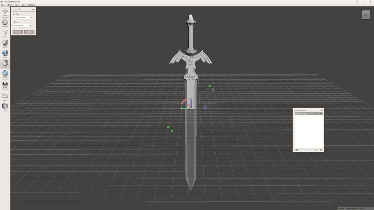
Next, you’ll decide where to split the model. Meshmixer’s Plane Cut function will give you two options: Cut or Slice. The Cut option will discard one of the parts, while Slice will allow you to keep both pieces when you split the model.
- Click the Edit button on the left-side toolbar, then select “Plane Cut”. The plane that appears can be controlled with ease by dragging it around and rotating it.
- In the pop-up menu, choose “Slice”, as we want to keep both of the parts.
- When you’re happy with the plane placement, click “Accept” to perform the slice.
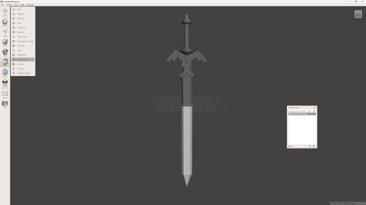
Step 3: Separate
Now, you’ll need to separate the two parts so you can move them away from each other. Click the Edit tab on the toolbar again, then select the “Separate Shells” option. The Object Browser should pop up and show you that there are now two separated objects.
At this point, you may be good to go! If the model is simple enough, you could export the model (see Part IV) and move on to printing it.
For some models, however, a simple split will not suffice when it comes time to join the pieces back together after printing. This is where adding keying (i.e. locater pins) comes in. By adding opposing features to either side of the cut, you can make them fit together like puzzle pieces, making them much easier to join together cleanly and in the correct orientation.
Part III: Add Keying
There’s finesse involved in gluing two pieces together when you’re trying to line them up perfectly. To avoid any kind of error, locator pins are here to help you. They facilitate lining up split parts while gluing them together. This prevents shifting or other errors.
You won’t find any dedicated tools or settings for locator pins in Meshmixer or Blender. A popular trick is to use a cube or a cylinder as the locator pin, but you could use any shape that makes the most sense for your project.
Locator pins are used by adding a shape halfway into one of the two parts and subtracting (inwardly recessing) the same shape from the other part. While a cylinder may appear to be an easy shape to use as a locator pin, cubes have a better chance of not shifting during the gluing stage.
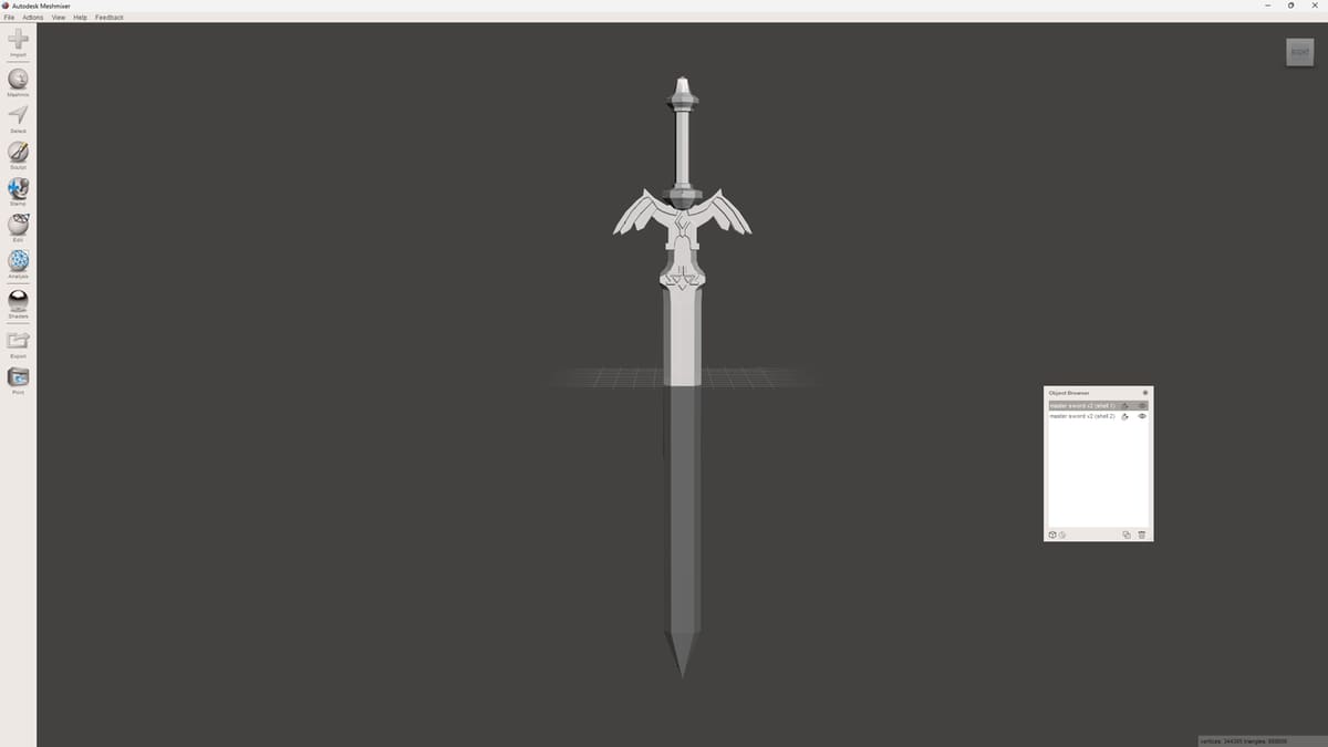
Step 1: Hide One Half
In this step, you’ll hide one of the halves. Before moving on, though, it’s essential that you make sure that both of your parts are aligned and haven’t been moved accidentally. Otherwise, you run the risk of adding locator pins that are not aligned.
Decide which part of the split model you want to begin with, then click on it or select it in the Object Browser. Hide the other split part by clicking the eye icon in the Object Browser.
If you close the object browser by accident, don’t worry. You can click the View tab at the very top of your screen, then select “Object Browser” to bring it back.
Step 2: Create the Locator Pin
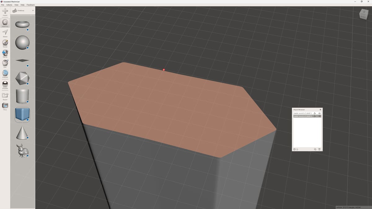
Now, it’s time to select a shape you’ll use as your locator pin:
- Click on the Meshmix button on the left-side toolbar. It’ll let you select from several simple shapes that you can use as your locator pin.
- Select a shape, then drag and drop it on the middle of the area that you split.
- Resize the shape so that it works best for your model.
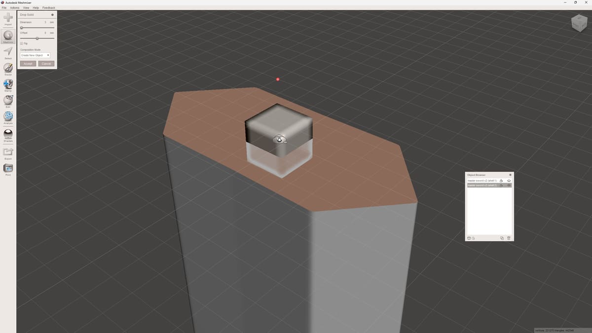
After you place the locator pin, a new pop-up window will appear next to the toolbar. The new window contains some options for how the mesh will be integrated into your model.
- Change the composition mode to “Create New Object”. This will prevent the shape from merging with either part of your model.
- Click “Accept” to place the object.
- Select the pin, then click the Copy icon at the bottom right of the Object Browser. You’ll now have two identical, overlapping pins.
- Hide one of the copies for now by clicking the eye icon next to it in the Object browser.
Step 3: Create the Pin Slot
Next, we need to create the hole in the half of the model that the pin will eventually slot into:
- In the Object Browser, select the half of the model you wish your hole to be in, then one of the pins we created. The order of the selection is essential: first the model, then visible locator pin.
- In the pop-up window that appears, select “Boolean Difference”.
- A secondary dialog window will open with a lot of options, leave it all at default and click “Accept”.
You’ll lose one of your pins, but its shape will be carved out of the model.
Step 4: Join the Remaining Pin to Other Split Part
This next step is really easy and not entirely necessary, but it avoids potential pitfalls later on. You just need to make sure that the remaining pin and the other part are treated as one entity in your slicer. This is to keep them from being separated by your slicer and the pin placed on the bed as a separate entity.
- Select the remaining pin and the other half of the model in the Object Browser.
- Make sure they’re both visible by toggling the eye icon.
- Select “Boolean Union” in the pop-up window and leave all the other settings at default.
- Click “Accept”.
Your pin and model half will now be one entity with no intersecting volumes so you won’t have to repair the model in your slicer later on.
Part IV: Export the Models
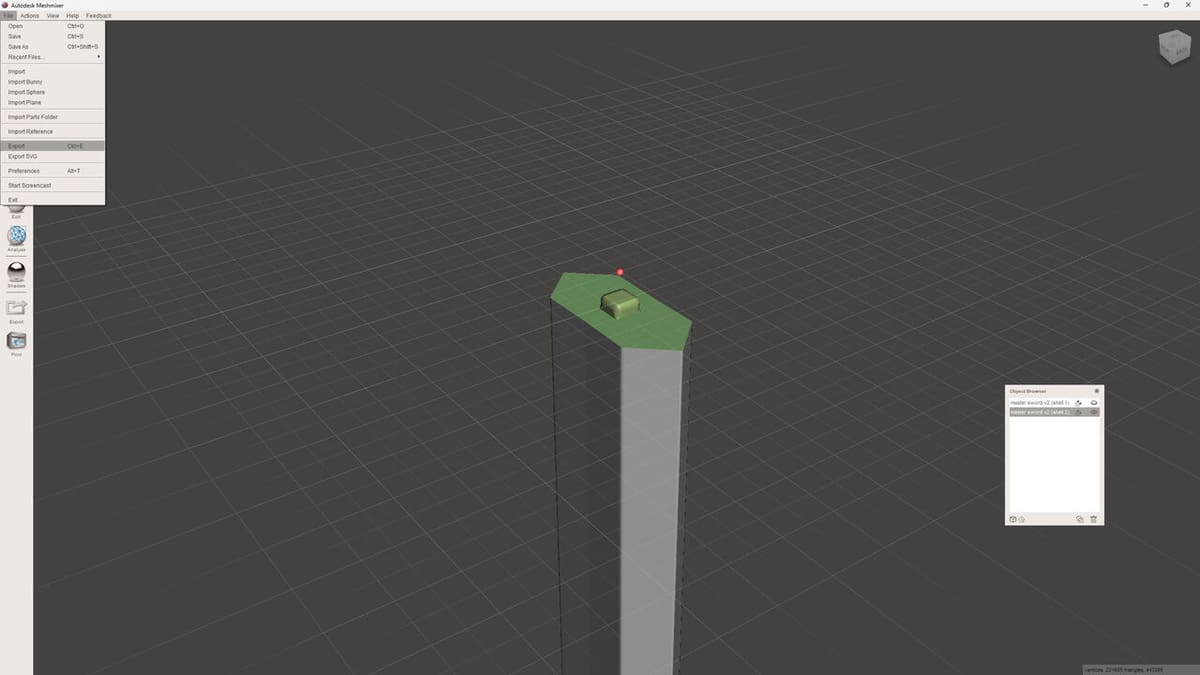
All that’s left is to export your model. In Meshmixer, you can export your model as an OBJ, STL, 3MF, or a variety of other formats.
- Select whichever piece of the split model you want to export. You can do this by clicking either on the part itself or on the label of the part in the Object Browser.
- Click on the Export button on the toolbar.
- Name the model something descriptive to avoid confusion later on.
- Repeat the process for the other side of the split model.
Blender
Part II: Split the Model with Blender
Next, we’ll go through how to split a model, add keying, then export the split models in Blender. While it’s more complex, Blender gives the user a lot more freedom and is just a more powerful tool in general – abeit once you know how to use it.
We won’t go into the ins and outs of Blender’s user interface, but you’re welcome to check out the UI sections in our article on modeling in Blender.
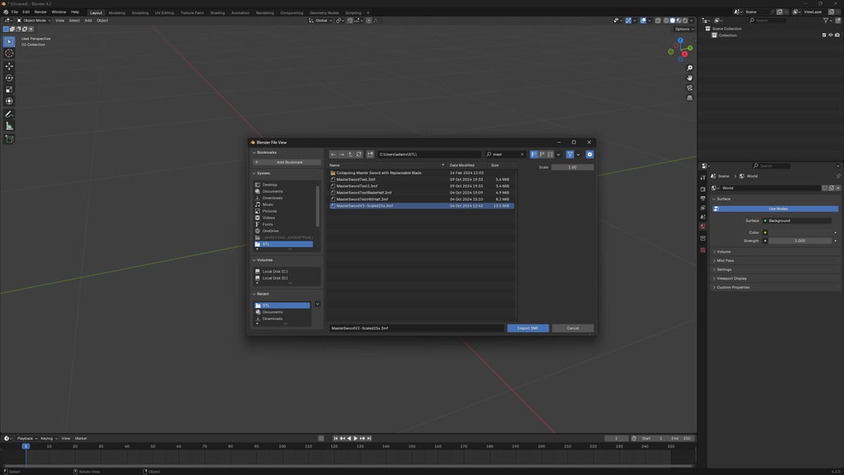
Step 1: Import
Blender is a bit more restrictive when it comes to supported mesh file formats. When it comes to common 3D printing file formats, it currently only supports STL and OBJ.
However, there’s an add-on called Blender3mfFormat that will allow you to import the 3MF format, a very common format in the 3D printing community these days. On the GitHub page linked above, there are easy-to-follow instructions on how to set this up.
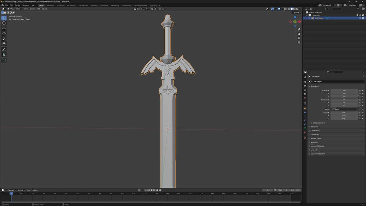
Once you have that set up, go to the File menu, select “Import”, then browse for the model you wish to import.
Step 2: Bisect
- Press ‘1’ on the number pad in order to get a head-on view of your model.
- On the left side of the Header, make sure you’re in Edit Mode. If not, press the Tab key or select “Edit Mode” in the Object Interaction Mode drop-down menu on the left-side of the Header.
- Now, select the model. It’s probably easiest to click the Select drop-down menu on the Header, then select “All”.
- Click and hold on the “Knife” tool icon on the Toolbar, then select “Bisect” from pop-up sub-menu.
- Find the spot where you want to split the model, then just click and hold the left mouse button to draw a line where you want to create the split.
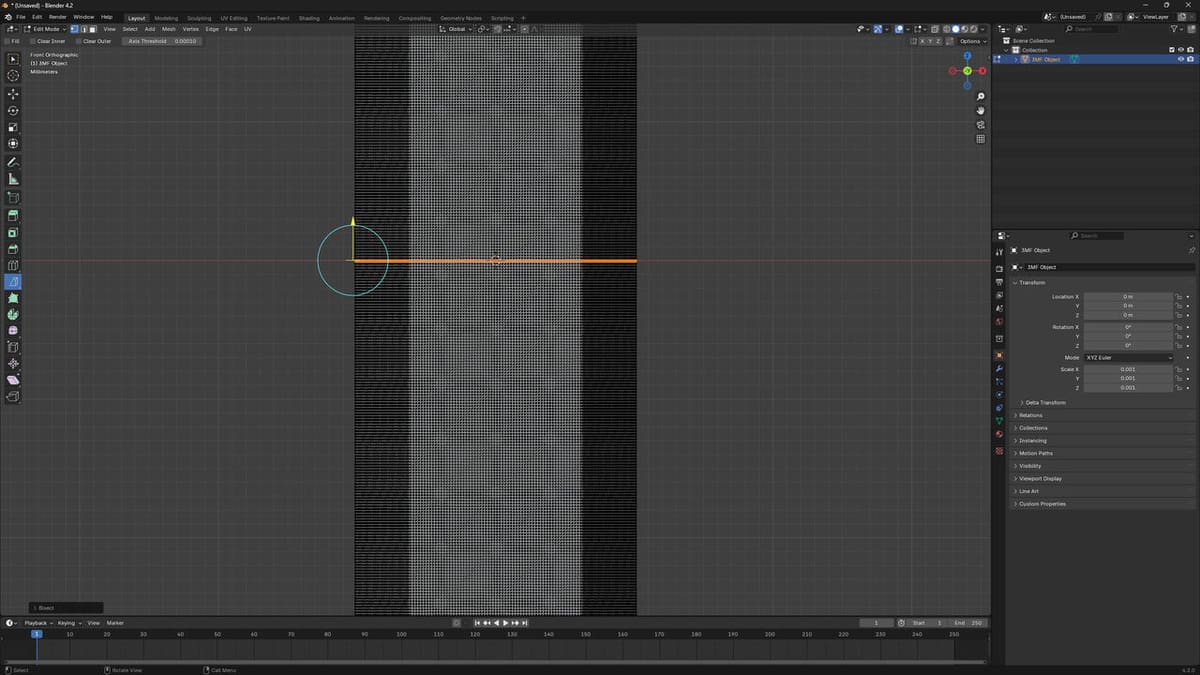
- Press ‘V’ in order to actually make the cut.
- Click the right mouse button, which stops you from dragging around the vertices.
- Click the Select drop-down menu on the Header, choose “Select Loops”, then “Select Loop Inner-Region”.
- Press ‘P’ on the keyboard to open up the “Separate” menu.
- Click on “Selection”.
You can then return to Object Mode, by pressing the Tab key, to move the parts away from each other and see the split.
Tip
If you want a nice straight cut, open up the Bisect Adjust Last Operation panel that appears on the lower right side of the interface. The enter ‘0’ for the Plane Normal X- and Y-axes values.
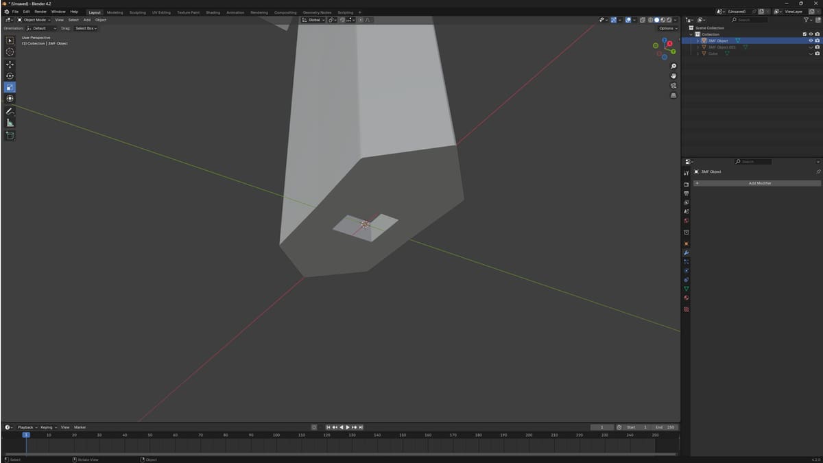
Step 3: Fill the Mesh
Now that your two halves are separated, you need to fill in the faces of the now open hollow mesh that we created with the cut.
- While in Object Mode, select one part of the split model.
- Then, press Tab to get back into Edit Mode.
- Hold down Shift + Alt, then click on the open edge of the model. This will select all of the vertices of the edge.
- Press the ‘F’ key in order to fill in the mesh with a new face.
- Repeat this for the other half of the model.
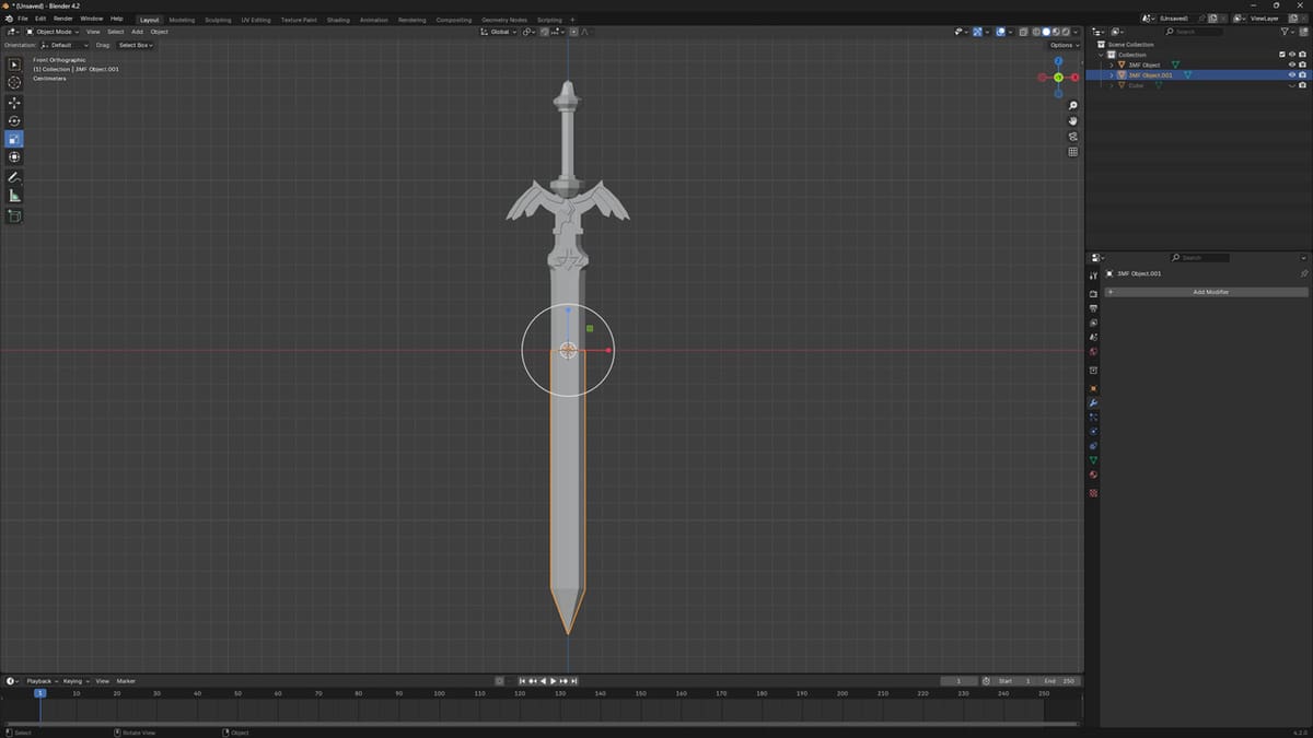
Part III: Add Keying
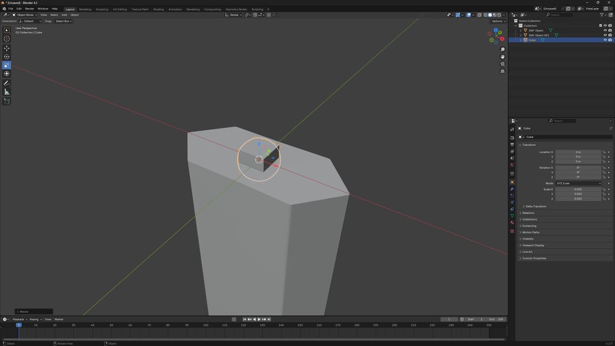
Step 1: Insert your Keying Object
- Press Tab to go back to Object Mode, then line up the two individual parts the way you want them to be.
- Once you’re satisfied, click the Add drop-down menu on the Header, then select “Mesh”.
- Select the shape you want to use as the locator pin. In this case, we’ll be using the cube.
- Use the Move tool on the Toolbar to move the cube into the middle of the two split parts as best as possible.
- Use the Scale tool to scale the cube to an appropriate size and change the dimensions of the cube in any way you’d like.
Once you have the locator pin how you want, it’s time to work with Boolean modifiers.
Step 2: Make the Slot
Boolean modifiers will let us bind or subtract an object from another.
- Hide one of the two parts by clicking on the eye icon beside its name in the Outliner Editor on the top right side of the interface.
- Select the other piece.
- In the Properties Editor on the bottom right side of the interface, click the Modifier Properties tab – the one with a wrench icon.
- Click “Add Modifier”, choose “Generate”, then “Boolean”.
- You’ll see three options: Intersect, Union, and Difference. Choose “Difference” if it’s not already selected.
- In the Object setting on the panel, select the locator pin.
- Apply the modifier by holding down Ctrl + A or clicking on “Apply” on the drop-down menu next to the modifiers name. This will subtract the locator pin from the model you chose.
Tip
In order to see the change in the model, hide the locator pin shape in the Outliner Editor. If not already set, it may also be helpful switch the Viewport Shading to Solid. It’s the third icon from the far right side of the 3D Viewport Header. You can also hover over the icons, and the type of Viewport Shading will be displayed.
Step 3: Make the Key
Next, it’s time to repeat the same steps for the other side of the split model. Reveal the hidden part and hide the part you’ve already worked on. The only difference is that you’ll have to shrink the size of the locator pin by clicking on it, pressing ‘S’, then moving your mouse towards the middle. If you want to be more precise with the scaling, you can adjust the value in the Adjust Last Operation panel that pops up on the lower left of the 3D Viewport.
The goal here is to shrink the key piece just enough to let it fit into the slot we created once the model is printed. The other place you’ll need to change is where you chose Boolean Difference. Now, you’ll choose “Union”, which will combine the two shapes into one piece.
Part IV: Export the Models
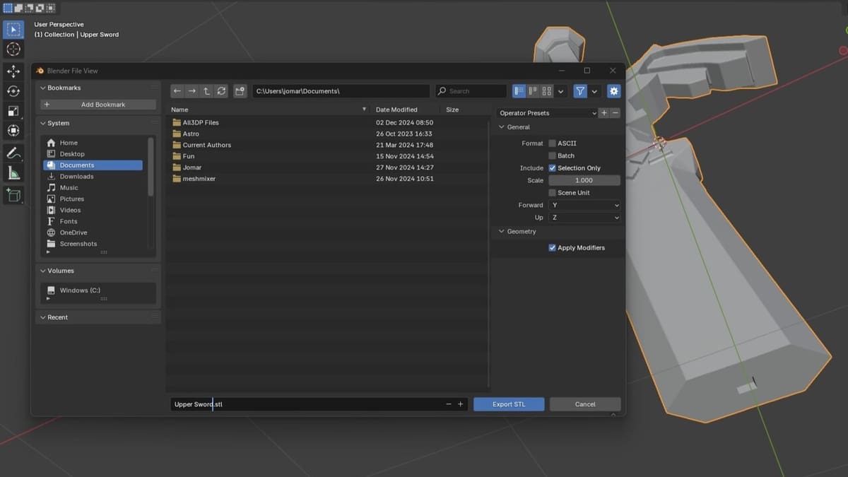
The last thing is to line up the models for how you would want them to be saved in the STL file. Then, under the File menu, choose “Export”, and select the type of file.
If you want to use the 3MF file format, you’ll need the 3MF add-on we downloaded and installed in Part II above. If you want to save your split model as two separate files, make sure only the desired object is selected, then check the “Selection Only” box when exporting.
Part V: Put Your Model Together
You’ve gotten this far! After you’ve printed your models, it’s time to assemble them. You may want to pick up some things to help you get the best adhesion when gluing your pieces together. Things like sandpaper, gloves, rubber bands or clamps, and some super glue activator spray may help make things easier.
Different glues can be used for assembling printed pieces. The most common is cyanoacrylate glue, referred to as super glue, for its ease of use, but it may not always be the best option depending on what you’re working with. Other options like epoxy and even using a 3D pen can be useful during assembly.
Another thing to consider is some sort of filler compound. While it’s useful for hiding layer lines, it can also help if you have a visible split line after gluing the two models together.
This is common when joining two separately printed pieces and can happen for a number of reasons. Sometimes, it’s due to elephant’s foot on one or both of the parts. It can also be caused when the keying of the parts isn’t quite perfect.
In any case, smoothing the transition point with sandpaper, then using some sort of filler compound can make the join invisible and seamless after painting. If you find yourself struggling with these steps or want to see more tips on improving the appearance of your finished models, check out our article on post processing 3D prints.
Alternatives
Slicers
Another way to split an STL is by simply using your slicing software. This is a very easy and convenient way to make a split. If you use Cura, you can check out this article on how to split a model in Cura for detailed instructions.
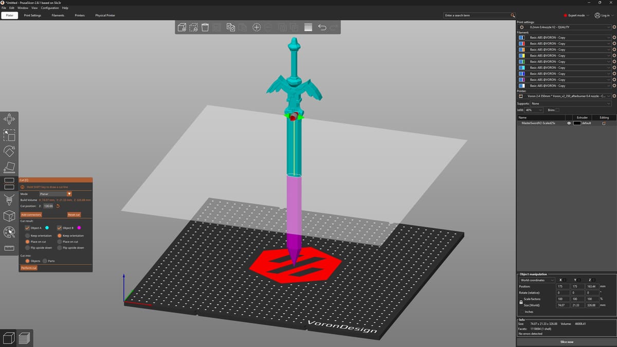
If you use PrusaSlicer, there’s a really handy feature called the “Cut” tool, which allows you to split a model, add keying features, and even add dovetail joints – all within the slicer. The tool is fairly easy to use, just select your model, then press ‘C’ to open up the Cut menu.
Here, you can drag around a plane that defines the area you want to cut along, and there are also a lot of other options to play around with. Check out Prusa’s detailed documentation on the Cut tool if you wish to learn more.
This feature is also present in Orca Slicer, and a more cut-down version of the Cut Tool (pardon the pun) is available in SuperSlicer.
Fusion
If you know and love Meshmixer, you might also appreciate Fusion (formerly known as Fusion 360). Back in September 2021, Fusion adopted a lot of the features that were available in Meshmixer.
With Fusion, you’ll have a lot of options for different planes and features to use when you split your model. Plane Cut and Separate are probably the ones you’ll want to focus on when you first start.
It’s worth noting that Fusion isn’t quite as straightforward as Meshmixer and has a completely different UI layout as well. While there’s a considerable learning curve, Fusion’s YouTube channel comes packed with a lot of useful tutorials to advance your skills.
Mac users rejoice, for this will be a good alternative to Meshmixer! And with Fusion, you’re not limited to just splitting your STLs, as it’s a full-functioning CAD program.
License: The text of "How to Split an STL File / 3D Model for 3D Printing" by All3DP is licensed under a Creative Commons Attribution 4.0 International License.