IGES File Format – Simply Explained

They're not new, but IGES files are useful for storing 2D and 3D designs. Learn about the history and capabilities of this file format.
There are tons of file formats dedicated to different purposes, from storing web images to transferring 3D model information across other platforms, and new formats are regularly released for different purposes. However, some of the older formats, even including the STL format, are still very popular for their powerful capabilities and unique benefits.
Nowadays, there are many options for storing 2D and 3D information from computer-aided design (CAD) software. While older than many of its alternatives, the Initial Graphics Exchange Specification (IGES) format is still a great option for storing 2D and 3D data and transferring it across different CAD programs.
In this article, we’ll go over the IGES format to give you some insight into why you might want to use it for your designs. We’ll first review the history of the format and then dive into the capabilities that make the format useful. Lastly, we’ll compare the IGES file to other formats, showcasing the strengths and weaknesses of the format against the alternatives.

History
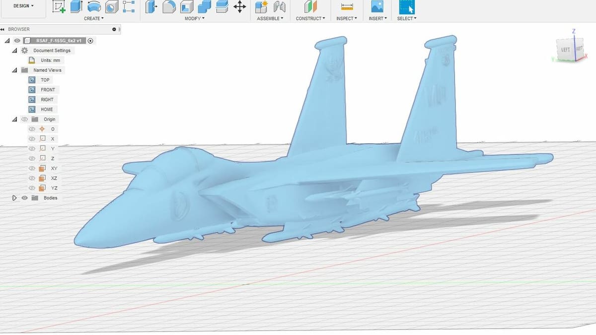
The IGES format was initially developed by the United States Air Force and published in 1980. The format was a product of the Integrated Computer-Aided Manufacturing (or ICAM) project, which sought to lower manufacturing costs by integrating operations. The IGES file was made to allow for aerospace-related designs to be transferred across different platforms with minimal data loss.
Before the IGES format, CAD and computer-aided manufacturing (CAM) software applications created by different companies had very little compatibility. Developers of different programs had no incentive to support another organization’s file format because this would make it easier to use the competitor’s platform.
This made it difficult for someone to take a design made in one company’s software and transfer it to another design or manufacturing application. And even if a design could be sent to another program, often the model wouldn’t have all of its features because the data wasn’t interpreted properly.
The IGES format was made to be vendor-neutral so users could send certain digital assets from a CAD program to a CAM program, regardless of who developed the application. For a time, the United States Department of Defense only signed contracts for designing applications that supported the IGES format, forcing developers to get on board.
Capabilities
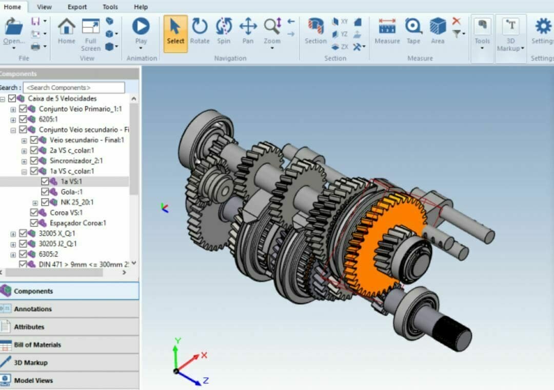
Although it’s older than formats like STEP and STL, the IGES format is very powerful. First and most importantly, it can store a fair amount of different CAD data, including circuit diagrams, wireframe designs, freeform surfaces, and solid 3D models. Even compared to more recent proprietary CAD formats, this is a lot of different types of CAD data that the IGES format can store and transmit across multiple CAD and CAM applications. However, it’s worth pointing out that, while IGES files can store surface geometries, it’s generally better for storing solid models rather than surface geometries.
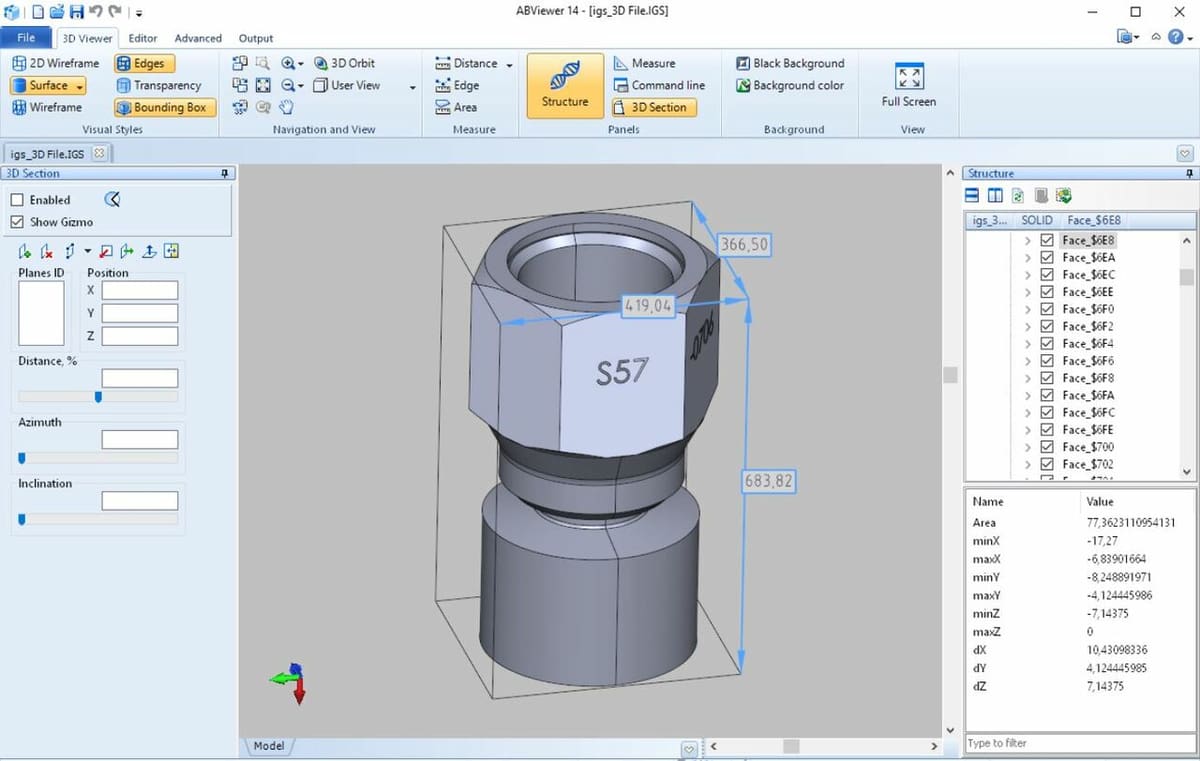
Second, the format is considered accurate when storing 2D and 3D data. 2D and 3D designs are processed as encoded curves and surfaces, a very accurate way of processing designs. This means manufactured parts will come out very close to how they appear digitally.
The IGES format is also vendor-neutral, so you can store and open the same types of data across multiple platforms even if they were created by different developers. This is why the IGES format is very popular for transferring digital assets between CAD and CAM programs, because manufactured models preserve the same features as the original design. Unfortunately, it’s known to be difficult to convert an IGES file to another format and back again without quality loss.
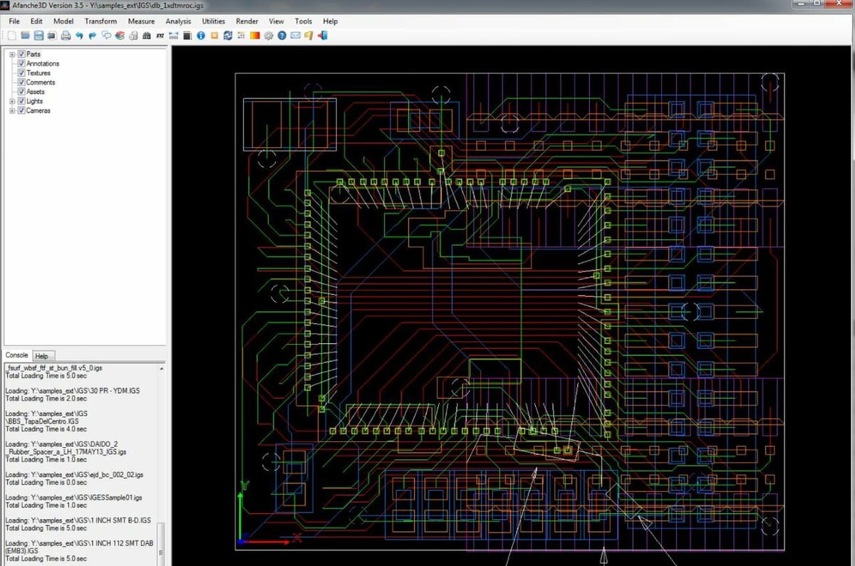
Another important characteristic of the IGES file is that it’s a vector format. Vector formats are typically associated with image file formats (e.g. SVG), but it’s important to remember that the IGES format stores 2D data like a circuit diagram. As a vector format, you’ll be able to scale IGES files with lossless quality, unlike raster formats that experience a drop in image quality.
One surprising benefit, perhaps, is that the IGES format supports multiple languages even though it was made by the US Air Force. Like other text-based formats, IGES files have a set of underlying code that defines the data stored in the file. While, originally, the text could only use Latin characters, as the format became more popular internationally, support for other characters like Kanji was added.
Accordingly, because the IGES is a text format, it takes more space than some other formats, like those that use binary. However, as a text format, it’s easier to make edits to an IGES file’s underlying code if you want to make technical changes.
As you can tell, the IGES format is a versatile format with many features. However, we can’t know if the format is a great option without comparing it to some major alternatives, STL and STEP files.
IGES vs. STL
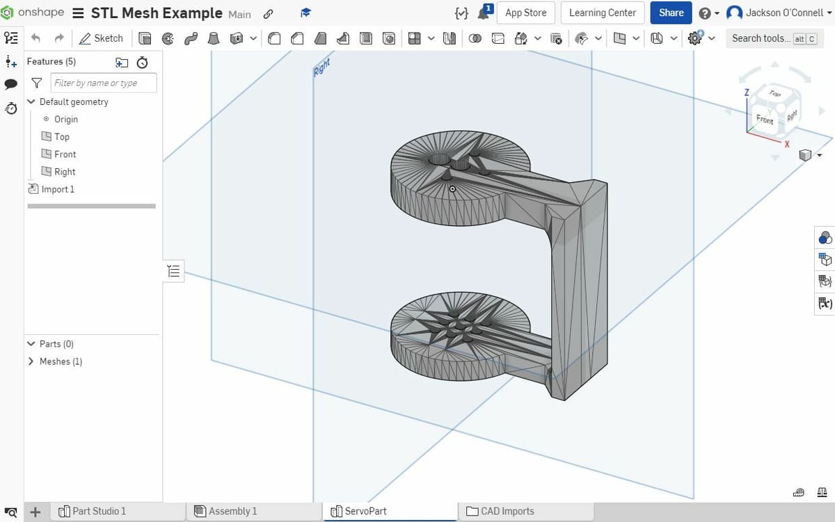
Especially if you have a 3D printer, you’ve probably heard of an STL file. Originally released in 1987, the STL format is one of the most popular formats for storing basic 3D models. STL files store the outline of a model’s structure as a set of triangular faces that are defined by vertices connected by edges.
While these days the STL format is more popular for storing 3D models and is supported by more CAD and CAM programs, the IGES format technically stores models with a higher degree of accuracy. The IGES format also stores a lot of additional CAD data, for example, circuit diagrams, making it useful for a wider range of applications.
When it comes to storage, though, the STL format takes the cake over IGES files. STL files can be saved in either a text or binary format, an option you don’t have with an IGES file. Because binary files take up less space than text formats, the STL file is a better option for those concerned with storage space on their device.
Overall, the STL format is probably a better option for those who want to store models they plan to 3D print because STL files are compatible with relevant software such as 3D model slicers. However, if you’re designing items other than solid 3D models, such as a wireframe structure, and you’re not concerned with storage space, then the IGES format is the more suitable choice.

IGES vs. STEP
The STEP file format is another popular option for 3D models and is considered a successor of the IGES format. STEP files store 3D models as single solid bodies, making it easier to edit parts across different CAD programs. STEP files also use NURBS curves to calculate curves on 3D models, making the format more accurate than the IGES format when it comes to storing 3D models.
While the IGES format can store more types of digital assets than the STEP model, for example, circuit diagrams, STEP files can store more 3D model data. The STEP format stores the geometry of a 3D model as well as its material properties and dimensional accuracy, a characteristic the IGES format lacks.
With this in mind, the STEP format is probably the better option for those designing 3D models between multiple CAD programs due to the increased 3D model data and accuracy. On the other hand, the IGES format is better for those who want to be able to store 2D and 3D data and are transferring models between CAD and CAM programs.

License: The text of "IGES File Format – Simply Explained" by All3DP is licensed under a Creative Commons Attribution 4.0 International License.