If you’re looking to upgrade your 3D printer, one of the most popular ways to do it is by changing the firmware. The two most popular options for this, Klipper and Marlin, offer a great deal of customizability and features that can be personalized to your use case.
More and more users every day are changing the printer’s default firmware to Klipper. This requires another round of new calibrations, and bed mesh isn’t an exception. This crucial feature can sometimes mean the difference between a successful print and a failure, so getting it right before printing is therefore a must. In a nutshell, if a bed surface is irregular – with bumps or dips, or if it’s in any way askew – then a bed mesh calibration will make up for this unevenness, avoiding issues with the first (and subsequent) layers.
It all sounds almost magical on paper, but how difficult is it actually? If you’ve already done it in Marlin, good news: it’s practically the same process with slightly different names.
In this article, we’ll go over how to set up the configuration file, how to execute the calibration procedure, and finally look into a few more advanced settings you might find helpful when working with Klipper. Stick around to learn more!
The Workflow
In essence, bed mesh compensation comes down to three steps:
- A set of instructions is given to the printer to probe the bed.
- A calibration sequence follows, and the results are stored in memory as a matrix of values.
- A command in the start G-code retrieves these values and instructs the printer to compensate for them.
Let’s take a closer look to understand what makes bed mesh compensation so effective and why you should calibrate it! And before we calibrate the mesh, we’ll briefly go over how to physically level the bed with the help of an immensely helpful macro that Klipper provides.
Bed Mesh Compensation
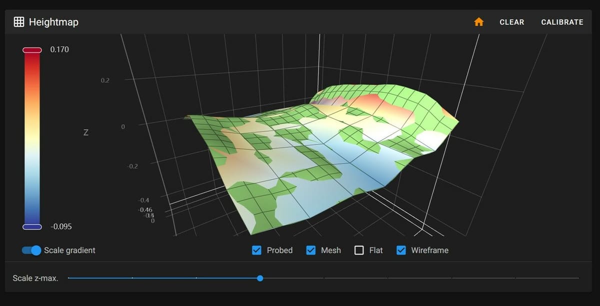
Even if squared to the gantry, no build surface is perfectly flat. It has lower and higher points, and this affects the first layer. The nozzle will inevitably be further away in some points and too close in others, resulting in uneven deposition of filament. This will cause all sorts of problems, like poor first layer adhesion, warping, uneven bottom layers, and much more.
To prevent this, the mesh compensation uses a set of values and coordinates to account for such imperfections. The nozzle is moved up and down to follow the profile of the bed and extrude at a constant distance from the surface.
Klipper offers two options for calibrating the bed:
- Automatic: This compensation uses a probe (BLTouch, CR Touch, capacitive probe, etc.). While it yields the most uniform results, it requires additional hardware.
- Manual: For this method, the user has to estimate the value by using a piece of paper or a feeler gauge and jogging the Z-axis up and down. This can be performed on any printer without the need for probes, but it tends to be less precise and more tedious.
Whatever method you choose, it won’t affect how the mesh is processed or compensated for.
Also, remember that this is just compensation. It doesn’t fix mechanical or squaring issues and it has its limits. An extremely warped bed will be more complicated to adjust for, and a skewed X-axis will inevitably reflect in the mesh. Before starting the procedure, remember to level your bed, as well as check that your gantry is squared.

Leveling & Tramming the Bed
The more askew your bed is, in relation to the gantry, the less effective bed mesh compensation will be. So it is important to dial this in before moving forward with the calibration procedures. If you have a print bed with leveling knobs, now is the time to get them all adjusted properly.
Klipper now has a really handy tool to help with this task, a macro called “Screws Tilt Calculate”. To use it, you need to provide the approximate XY coordinates of the bed leveling screws under the bed, along with the number of turns it takes to move your screws through their full range of motion. To find the screw coordinates look at the bed edge-on and measure from the edge of the bed to the screw location in both the X- and Y-axes. The number of screw turns can be found by turning them by hand through their full range of motion and counting the rotations. Neither of these values needs to be exact, so don’t worry to much about taking perfect measurements.
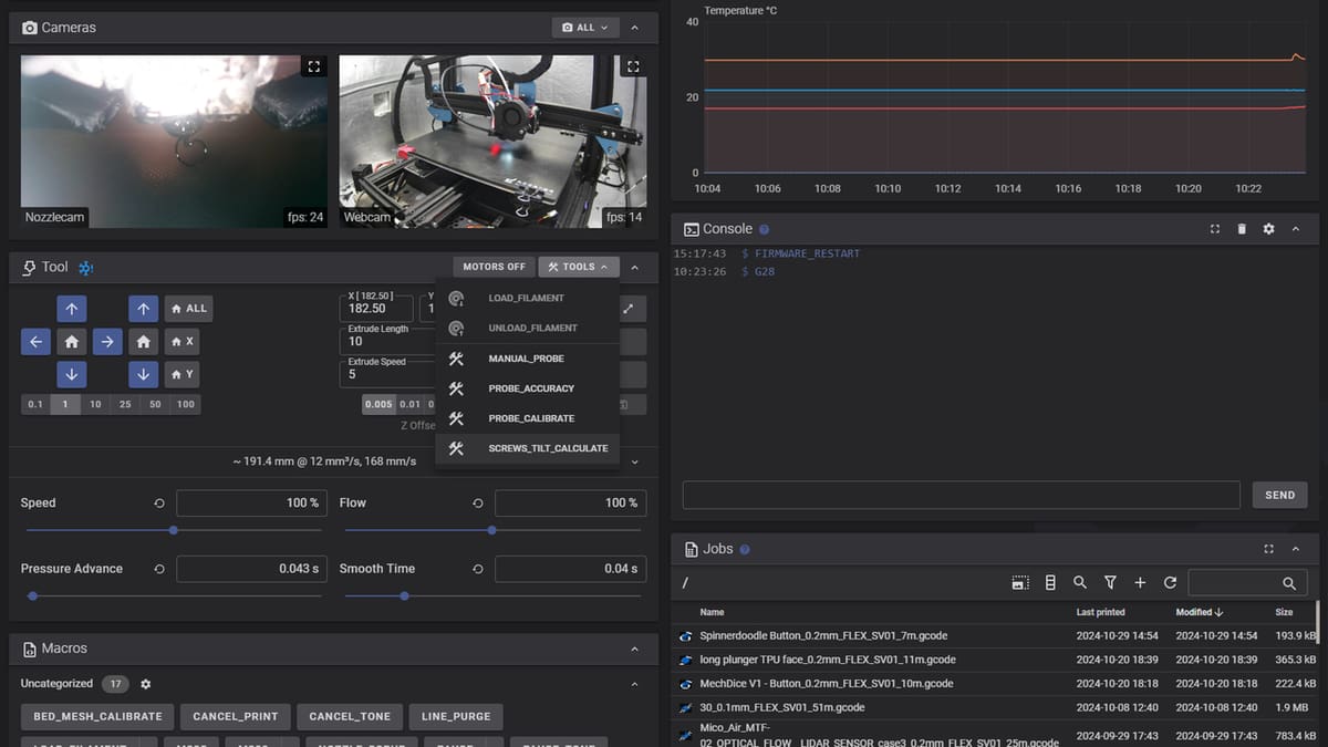
Then you can enter SCREWS_TILT_CALCULATE into the console or run it from the convenient button in Fluidd. Once you do, it will go through and probe each corner and provide a Z-height value, along with a suggested number of turns, clockwise or counterclockwise, to turn each screw in order to make them equal heights. Go through this procedure a few times or until the difference between each corner is ±0.05 mm.
For CoreXY machines, where the gantry or bed is moved in the Z direction with individual stepper motors, bed tramming is more or less automated with procedures like “Quad Gantry Level”. As long as your printer is mechanically sound, you should be ready to move on to generating your bed mesh.
How to Calibrate the Mesh
Now that you’re set and ready to calibrate, let’s dive into the steps to take. For reference, we’ll be using Mainsail for the interface, but Fluidd or OctoKlipper will work too.
Automatic
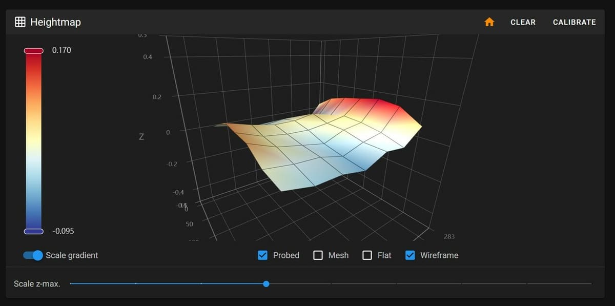
This method has several entry points: You can use the Calibrate button in the Heightmap menu, create a macro to run it, or send each command via the Console. Again, the execution doesn’t have any effect on how the mesh itself will be measured. It’s only a matter of interfaces and buttons.
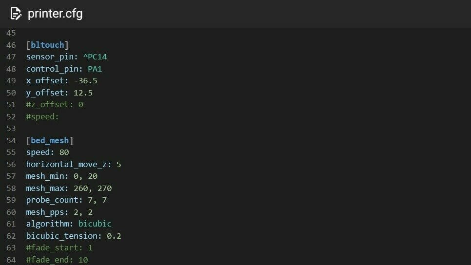
The first step is always to create the [bed_mesh] section in the config file. In this section, you will have to define:
- The boundaries – in the X and Y directions – for the probe (or the radius of the bed, in case of a round one).
- The number of points to probe per axis, X and Y.
- The speed of the probing movements.
For example, it could look like this:
[bed_mesh]mesh_min: 5, 5mesh_max: 215, 215probe_count: 7, 7speed: 80
Everything is explained in detail in Klipper’s Configuration Reference. Make sure to check it out beforehand.
The included Calibration button under the Heightmap (or Bed Mesh in Fluidd) menu will execute whatever you have set in [bed_mesh]. This fire-and-forget option will work fine for a rapid automatic calibration.
Alternatively, you can also create a macro in the config file. This will allow you to manipulate the calibration sequence, for example, by homing the printer first or by heating the bed. This way, you can also run it automatically at the start of every print.
To learn more about Klipper macros, you can read the corresponding Command Templates.
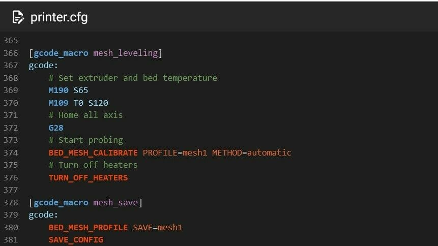
For example, a macro that heats the bed and nozzle before printing could look like this:
[gcode_macro probe_mesh]
gcode:
       # Set extruder and bed temperature
       M109 S120
       M190 S60
       # Home all axis
       G28
       # Start probing
       BED_MESH_CALIBRATE PROFILE=mesh1 METHOD=automatic
       # Turn off heaters afterward
       TURN_OFF_HEATERS
Finally, you could also simply give the command via the Console terminal to execute the calibration. You can follow this structure:
BED_MESH_CALIBRATE PROFILE=<name> METHOD=[automatic] [<probe_parameter>=<value>] [<mesh_parameter>=<value>]
probe_parameter and mesh_parameter indicate the aforementioned values to set. Use MESH_MIN, MESH_MAX, and PROBE_COUNT to define them. Here’s an example:
BED_MESH_CALIBRATE PROFILE=mesh1 METHOD=automatic MESH_MIN=5,5 MESH_MAX=215,215 PROBE_COUNT=7,7 PROBE_SPEED=80
Always remember to save your mesh!
Manual
After you’ve created the [bed_mesh] section in the config file, you can proceed with issuing the command via the Console or a macro, this time using METHOD=manual.
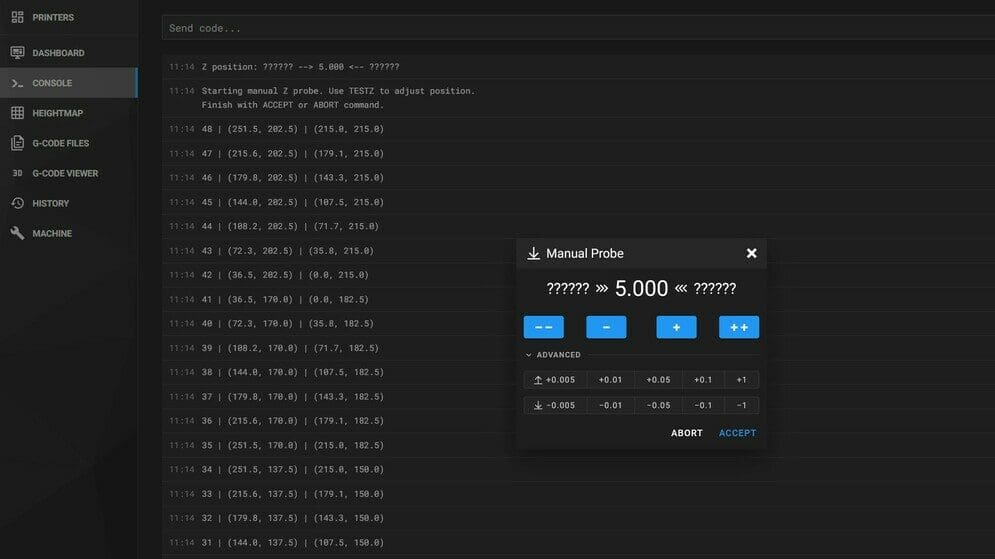
- This will start a procedure that will move the nozzle to each specified point.
- With the help of a feeler gauge or a piece of paper, you can then adjust the friction on the nozzle by moving the Z-axis up and down via the interface. Mainsail even has a specific window for this.
- When happy with the desired amount of friction, you store the value with ACCEPT (to issue in the Console) and move on to the next point. Repeat the process trying to reach a homogenous level of friction across all points.
- You can always stop the procedure by clicking on ABORT.
Once you’re done, don’t forget to save your mesh.
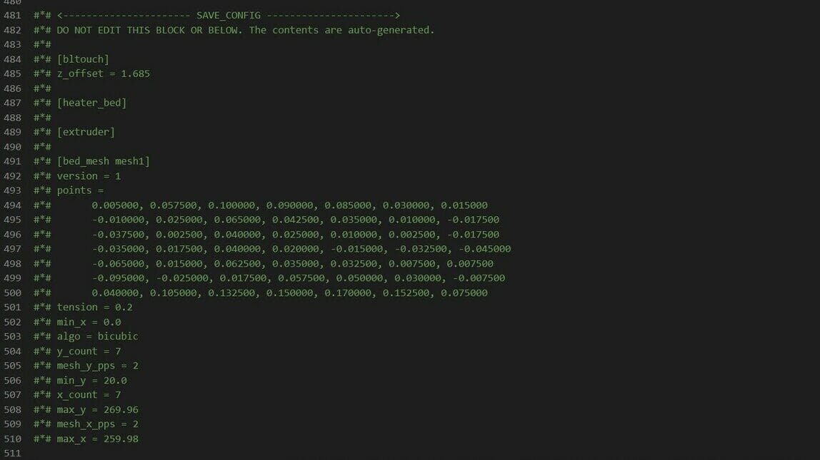
Save the Mesh
Always use the SAVE_CONFIG command to store the mesh and restart Klipper. The values will be saved at the bottom of the config file, under the SAVE_CONFIG section. You should not be editing that part.
How to Activate Mesh Compensation
There are a two main ways you can active mesh compensation. One includes using an existing mesh, the other creating a new one.
Using a Previously Generated Mesh
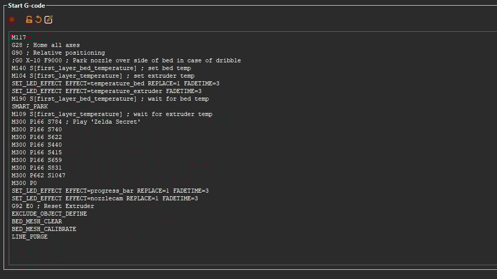
To be effective, the mesh has to be recalled before starting a print. You can do so by adding a few lines at the end of your start G-code, directly in the slicer, or in your START_PRINT macro. Here’s how that looks in practice:
BED_MESH_PROFILE LOAD=<name>
This will restore the mesh state from the profile matching the supplied name. It’s needed to activate compensation.
BED_MESH_PROFILE REMOVE=<name>
This can be used in the end G-code to delete the mesh stored. SAVE_CONFIG is needed afterward.
Remember that you need to set an appropriate Z offset to have reliable adhesion. You can learn more in our article on how to make Klipper and BLTouch work together.
Creating a New Mesh for Each Print
While in many cases using a previously generated mesh is adequate and can be reused many times, your printer will lose its alignment over time and make the mesh less and less accurate to its actual state. This is especially true for printers with bed leveling screws or where you have separate spring steel plates with different bed surfaces.
In order to make sure that your mesh is compensating for the current state of the printer, many users prefer to generate a new bed mesh for each print. This is a trade off, as it does take a significant amount of time to generate the mesh, but if you aren’t in too much hurry, it might just be the way to go.
First, it’s a good idea to use the BED_MESH_CLEAR command before generating a new mesh in order to ensure that your new mesh gets used for your print instead of a previously saved profile.
In order to generate a new mesh for each print, you will need to add the BED_MESH_CALIBRATE command to your start G-code macro or to the start G-code you specify within your slicer. The order is important here: It is recommended to add the macro after your bed has heated to temperature, as the beds surface changes significantly when heated. And note that the BED_MESH_CALIBRATE should be placed after the BED_MESH_CLEAR command, so you don’t delete your newly made mesh!
When using this method of generating a new mesh every print, it’s easy to adopt the mindset of “set it and forget it”, which is kind of the point. However, you shouldn’t forget to re-tram and recalibrate your Z offset every so often, so your mesh isn’t having to compensate for too much tilt. It’s a good idea to look at the mesh that is being generated occasionally to get an idea as to how much your bed is tilted or warped.
Advanced Options & Macros
While the aforementioned configuration will work fine, you might want to dive deeper into what the mesh module can do. In fact, Klipper includes a series of parameters and tools that might come in handy for more expert users:
- Mesh Interpolation: An algorithm calculates the middle points between two probe points, and adds them to the mesh. This allows the user to achieve a greater resolution with the same amount of points probed, particularly useful for very large beds.
- Move Splitting: For very uneven beds where the nozzle has to travel long Z distances, it’s necessary to split those movements into smaller ones. This option controls the splitting behavior.
- Mesh Fade: This progressively diminishes the amount of correction applied until it fades at a defined distance from the bed.
- Faulty Regions: This setting allows the user to define regions of the bed where the probe behaves unreliably (e.g. above magnets). Klipper will then probe four points outside of the region and average all of them.
For more on all of these settings and how to use them, always refer to Klipper’s configuration documents.
Some users have come up with very clever bed calibration macros that you simply add to your configuration file (with extremely light modifications). Among the most useful ones are these:
- Klipper Adaptive Meshing & Purging, or KAMP, which provides an automated script to probe only the portion of the bed where the print will be. It is an easy to implement time saver and includes a smart purging routine function as well.
- An automatic routine that calibrates the bed every 10th print, created by u/The_Red_Gobbo on Reddit.
License: The text of "Klipper: Bed Mesh – Simply Explained" by All3DP is licensed under a Creative Commons Attribution 4.0 International License.