Snapmaker Luban Software: How to Get Started

Snapmaker Luban is a free tool that will help you generate G-code for your 3D printing or laser cutting projects. Read all about it!
Snapmaker Luban is one of those tools that you don’t know about until you know about it. However, it’s been rising in popularity lately as one of the top straightforward tools for G-code generation. It’s gradually becoming the go-to solution for many people for their 3D printing, laser cutting, laser engraving, and even CNC carving needs.
The company behind this tool, Snapmaker, is perhaps best known for the incredible crowdfunding campaign that raised over $7.8 million for its flagship product, the Snapmaker 2.0 – the modular 3-in-1 3D printer, CNC mill, and laser cutter and engraver.
Snapmaker Luban is free, open-source, and is based on UltiMaker Cura (or “CuraEngine”), an application for 3D slicing. It’s marketed as a 3-in-1 solution tailor-made for the Snapmaker machines, but it can be used effortlessly with other similar machines as well. Its workflow is similar to CuraEngine’s, with the addition of laser cutting and engraving and CNC milling capabilities, as well as a few nice tools that are easily accessible from the UI.
In this article, we’ll go over everything you need to know about Snapmaker Luban, from its layout to its 3D printing, laser engraving and cutting, and CNC carving workflows.
The Program
Installing the software is as simple as it gets: go to Snapmaker’s site and download the installer for your OS, then run it, choose your download location, and click “Install”. The software is completely free and runs on Windows, Mac, and Linux.
Now that we’ve got Luban running, let’s look at how it works.
Layout
When opening the software for the first time, you’ll be prompted to choose a language and a machine model, and then you can click “Complete”.
Don’t own a Snapmaker 2.0? No worries! You can still use the software to generate G-code for other machines. A few things to keep in mind:
- Luban creates G-code in the firmware “flavor” (or format) of Marlin. To confirm the compatibility with your specific machine, this information is usually found in the product specifications sheet or on the manufacturer’s website FAQ section. (In any case, most 3D printers use Marlin-derived G-code.)
- Ensure that your 3D printer’s bed size is similar to one of the options included in the list, so as to not prepare things for a print that’s too big for the bed size.
- Make a tiny part or calibration cube as a test for errors first.
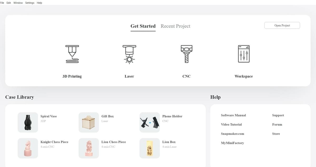
Next, you’ll be greeted with a screen showing four types of workflows, the “Case Library” on the lower left which contains some examples for each of the workflows, and some help resources on the lower right such as the Snapmaker website.
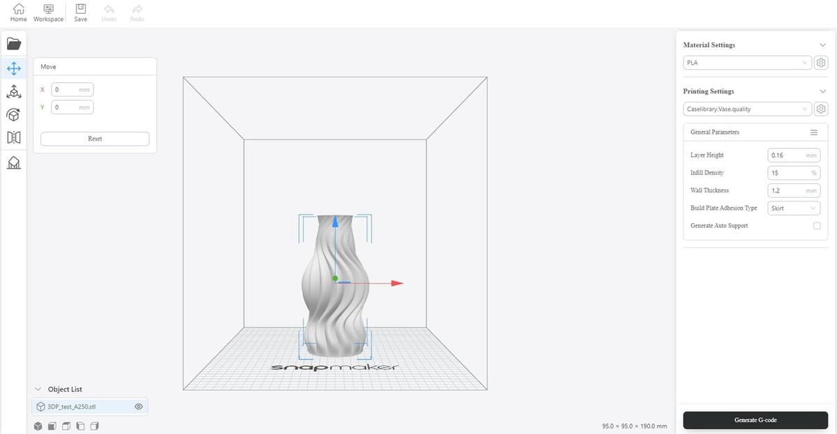
UI
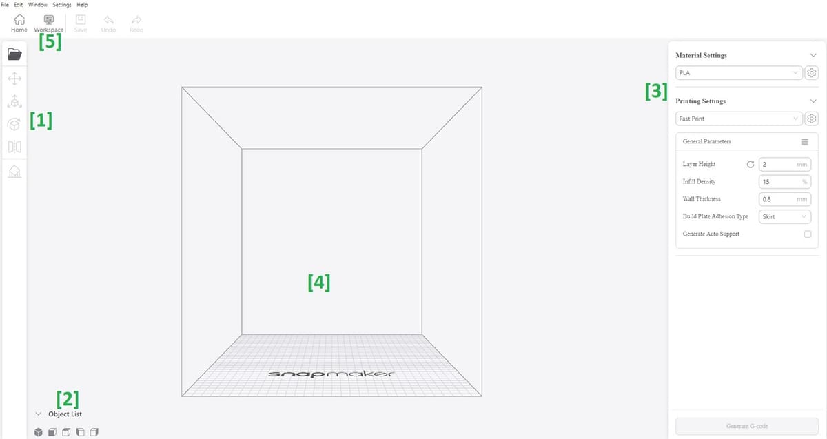
Clicking on the 3D printing icon, we catch a glimpse of the UI as shown in the image above. At first glance the UI is far from intimidating and is as intuitive as it gets.
The different parts show:
- The left-side toolbar is for some basic file and model operations. In order from top to bottom: Import (to import files), Move, Scale, Rotate, Mirror, and Add support, for the respective model operations.
- Quick view mode control, which allows you to change the perspective from which you view the model(s). You can also left-click and drag to rotate the view, or right click and drag to pan. With the wheel of your mouse, you can also zoom in or zoom out.
- Parameters area (the bread and butter of the software, which we’ll cover next).
- The model work area, where the magic takes place.
- “Workspace” links to a window where you can directly control the Snapmaker machine if you have one by, among other options, setting an origin point.
Settings
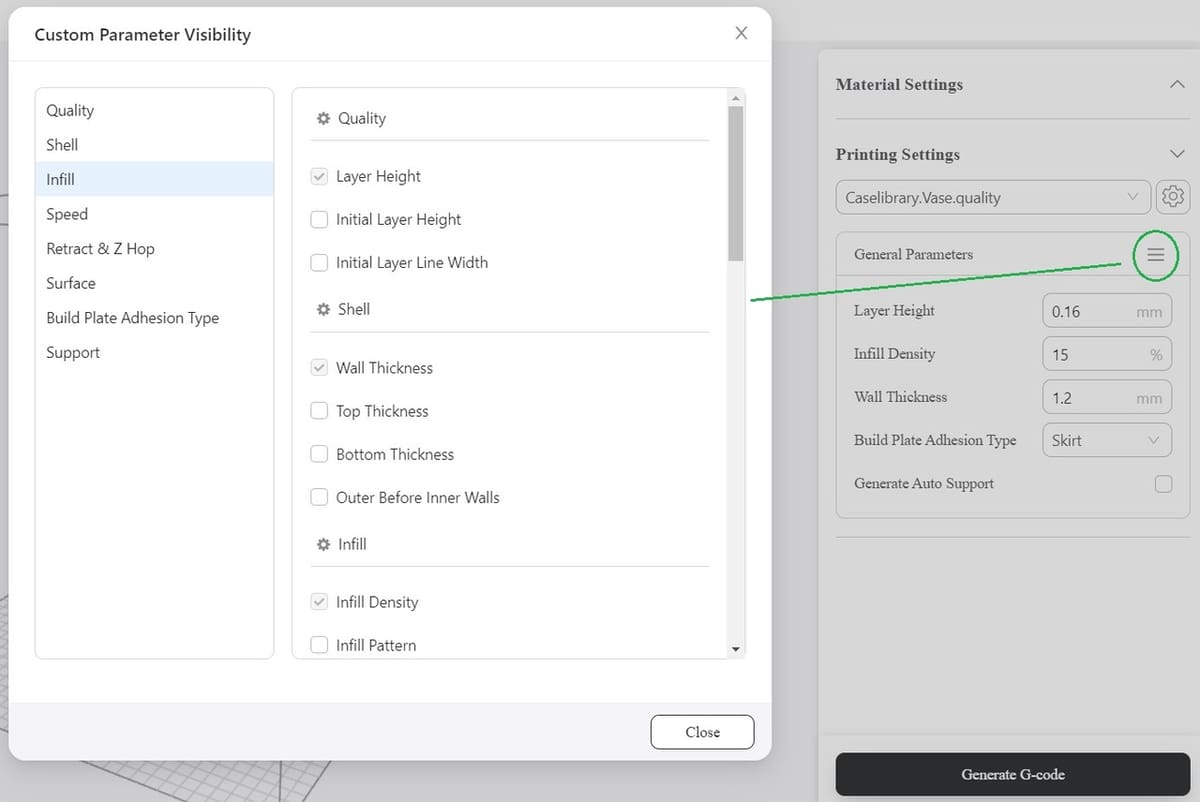
Another nice option to have in this UI is the ability to customize which printer settings you can see. Just click on the three stripes beside the “General Parameters” subsection on the right and choose your favorite parameters to display.
For example, in the image above, set for 3D printing, we chose to show the layer height, wall thickness, and infill density by checking the boxes next to them because we use these particular settings more frequently than most. Other settings that can be modified with Luban include Quality (the initial layer height and width can differ from the rest of the print), Shell, Infill, Speed, Retract & Z Hop, Surface (similar to Cura’s Vase Mode), Build Plate Adhesion Type (skirt, brim, and raft), and Support, but in this tutorial we’ll be keeping things simple.
Now that we’re familiar with the layout, let’s dive deeper into one of the core functions of Snapmaker Luban: 3D printing.
3D Printing Workflow
Now that we’ve gotten our bearings in Luban, let’s get working on our first G-code!
Before getting started, you’ll need an STL or OBJ file that you’d like to 3D print. There are plenty of sources if you’re not up to designing one yourself. For our part, we chose a vase model that came with the software, as well as a classic Benchy. We chose to do both in one run to demonstrate different Luban capabilities.
Importing a 3D Model
Importing your favorite 3D model (OBJ or STL) is as easy as one-two-three (okay, maybe more like one-two-three-four, but still):
- Be sure to check the bed dimensions in the machine you selected by going to “Settings > Machine Settings” in the top bar. Make sure that they’re the correct bed dimensions, to avoid differences between the software simulation and reality. We don’t want a model that’s bigger than the machine bed in reality.
- Next, go to “File > New Project > 3D Printing”.
- Click on the Folder icon to import a file.
- Be sure to select an STL or OBJ file, then click “Open”.
Moving & Scaling
For a few simple model adjustments:
- Select the model with the left mouse button – it should be highlighted by blue borders.
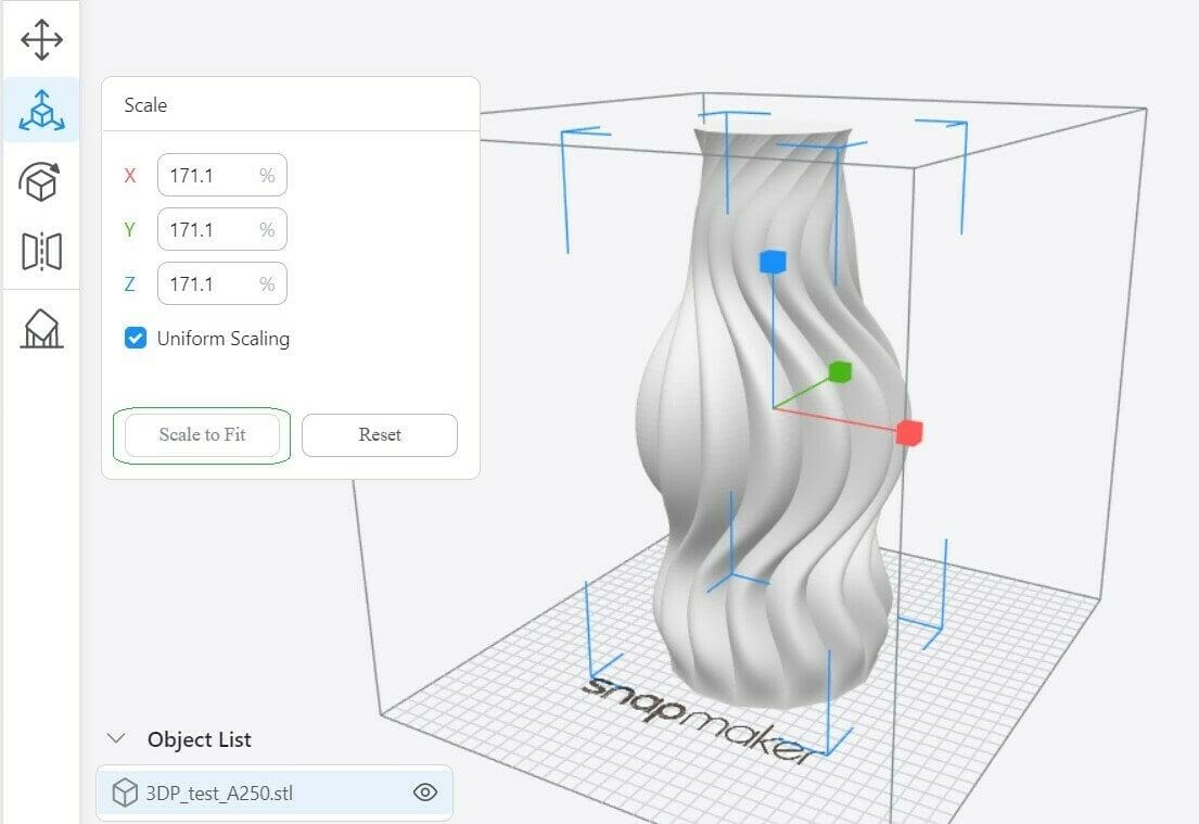
- If you want to scale the object, you can click on the Scale icon on the left toolbar (below Move), then either change the number values or drag any of the three arrows to scale in the direction of each axis.
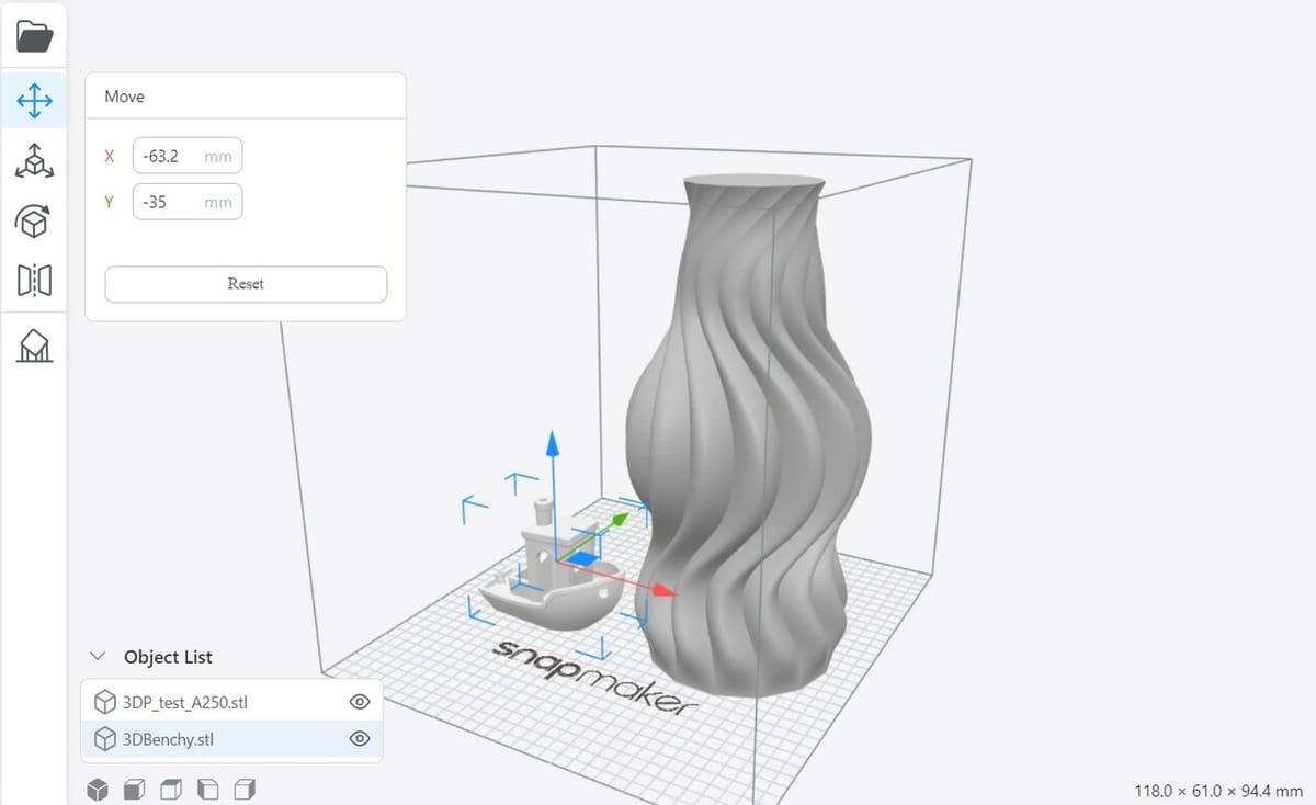
- Because we’ll be adding the Benchy, we’ll click on the Move icon and relocate the vase a few centimeters in the X direction to the right, either by dragging the arrows or by writing the distance. If you’re only printing one object, this isn’t necessary. Moving the object may be necessary if it’s especially extensive and it doesn’t fully fit on the print bed without some readjusting.
- Click anywhere on the workspace to deselect the model (there shouldn’t be any more blue borders).
- Then we follow the previous steps to import a Benchy.
- With both models on the print bed, we scale the Benchy and drag it next to the vase on our workspace according to the needs.
- Once the objects have been placed and scaled according to the printing objective, it’s time to look into the settings.
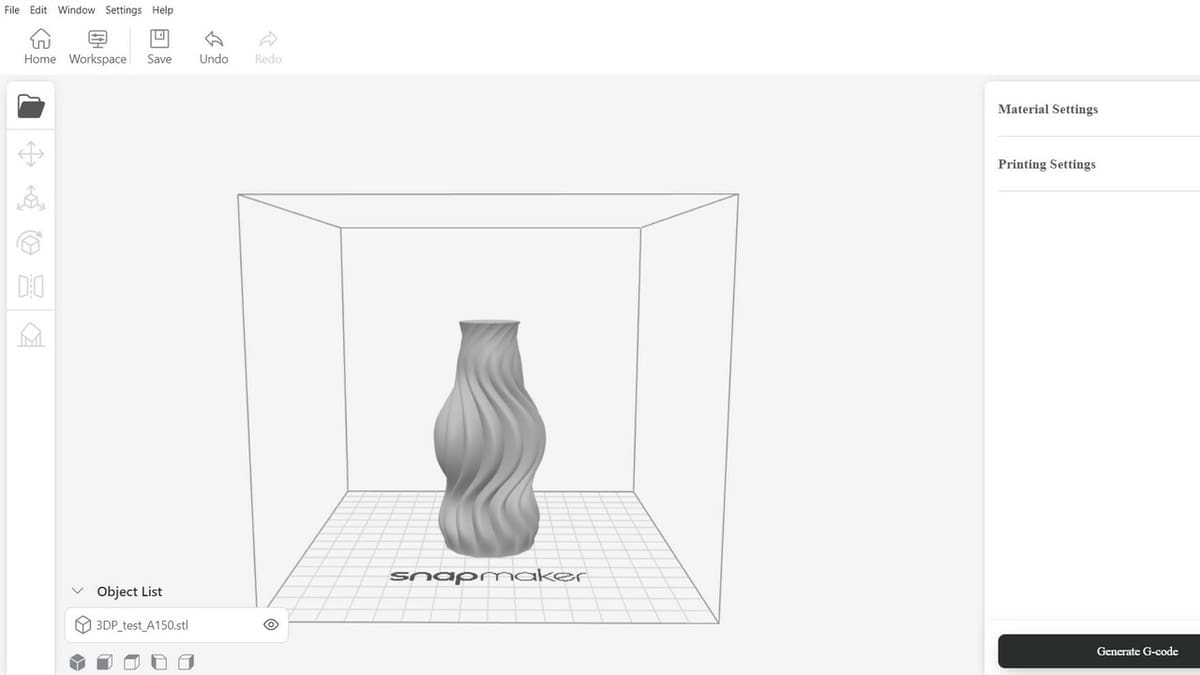
Object List
If you look closely in the previous image, to the lower left side of the screen you’ll see an object list, which now contains two items.
By selecting the Benchy, we can see its overall dimensions on the lower right part of the screen, to get a sense of how big or small the part is. The information will change depending on the model you’ve selected.
The Settings
There are a few things that can be tinkered with in Luban.
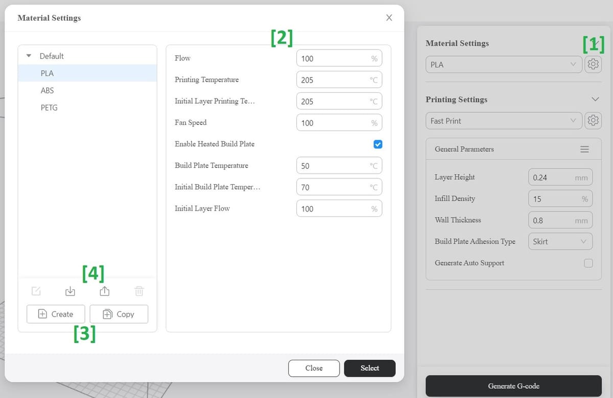
- We’ll head over to the “Material Settings” section on the right toolbar; for our purposes, we’re opting for PLA, which is an existing preset (a set of saved typical settings that are used most of the time) – but it wouldn’t hurt to check the actual parameters such as the printing temperature (nozzle temperature) or the bed temperature. So, we’ll click on the Settings icon in the Material Settings section.
- A window pops up that summarizes our printing parameters for PLA and allows us to edit them.
- We can save the presets with the edited parameters, to be able to get back to them later when we’re working on a new project. This saves a lot of time when using the same framework repeatedly. We can also create new presets with different values if we want to.
- Presets can also be imported to and exported from JSON files. JSON files are a type of configuration file that can be edited manually through a text editor or by importing them to software that reads them, like Luban. If you wanted to change the configuration file through a text editor and not through software, it’s generally easy to do because the JSON configuration file is written in fairly readable language.
- Next, we choose the printing parameters. Because the vase is quite big, time may be an issue. We go to Printing Settings on the right and, from the drop-down menu, choose the “Fast Print” preset.
- This isn’t necessarily the best option for any big print, as too-speedy printing can lead to issues, so check the best settings for your design and material of choice.
- Same as we did in the previous steps, we click the Settings icon next to Printing Settings just to confirm that all the values are within the range we intend them to be (mainly the layer height, wall thickness, and infill density). You also have the option to create new presets here if there are specific settings that you know you’ll be working with in the future.
Generating the Print G-code
We’re almost done!
- Now that everything’s in order, click “Generate G-code” on the lower right.
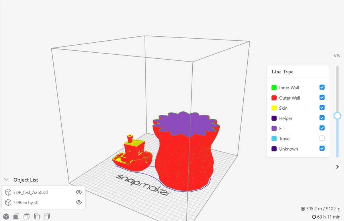
- After a few seconds, the models’ colors change to indicate different aspects of the printing process. There’s also a slider to view the models’ sections.
- The colors indicate which part of the object we’re looking at: red indicates the outer wall, green indicates the inner walls, and purple indicates the infill. Yellow refers to the “skin”, which are the top and bottom layers of the print.
- On the lower right section of the screen, along with the filament length required, you can find the print time. In our case, as expected for the size of the vase, it’s quite a lengthy print.
- You can also click on “Close Preview” on the lower right when you want to go back to the regular model view.
- Finally, click “Export > Export G-code to File”, and your code file is ready.
All that’s left is saving your G-code to the compatible SD card or sending it via Wi-Fi to your printer.
Now that we know the 3D printing workflow, let’s go over how to prepare G-code to laser cut or engrave using Snapmaker Luban.
Laser Cutting & Engraving Workflows
For the next part (and the part that earned the software many fans), we’ll look at how to use Luban for laser cutting and engraving. The software allows users to cut and engrave in one program, but if you want to only engrave or only cut, the workflow is the same.
This means we can set up our wooden sheet only once, and set up the different operations we wish to do with as many images as we like, then export only one program to the machine, with all the different operations written in the same G-code file to be performed sequentially. This is also easy to do for the machine because the main difference between cutting and engraving is just the power of the laser.
For this tutorial, we’re going to use two pictures, one is a vector image (by lukasiniho), and the other is a non-vector image (by Alexandra_Koch). If you’ve got other images that you’d like to work with, make sure to save them for easy access. We chose two images of different types because vector images are mainly used for cutting, while non-vector images are mostly used for engraving.
Getting Started
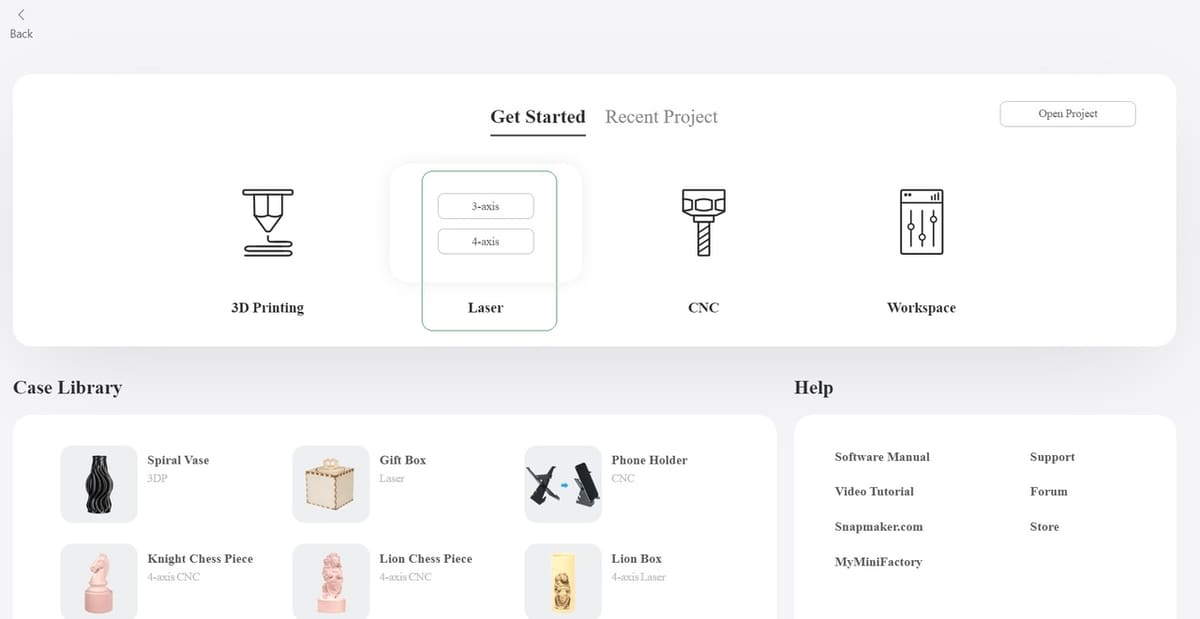
At the Home screen, click on the Laser icon and choose “3-axis” or “4-axis”, depending on your laser machine type. Most laser cutting and engraving machines are 3-axis, which is what we chose for the purpose of this tutorial. “4-axis” is usually used to describe machines that have a “rotating” part of the machine that rotates the workpiece, usually a cylindrical piece of wood, while the laser tool head moves around to make the engraving.
As with 3D printing, as a general rule of thumb, G-code is a standardized language, so the file should work fine on most laser cutters and engravers.
Importing a Non-Vector Image
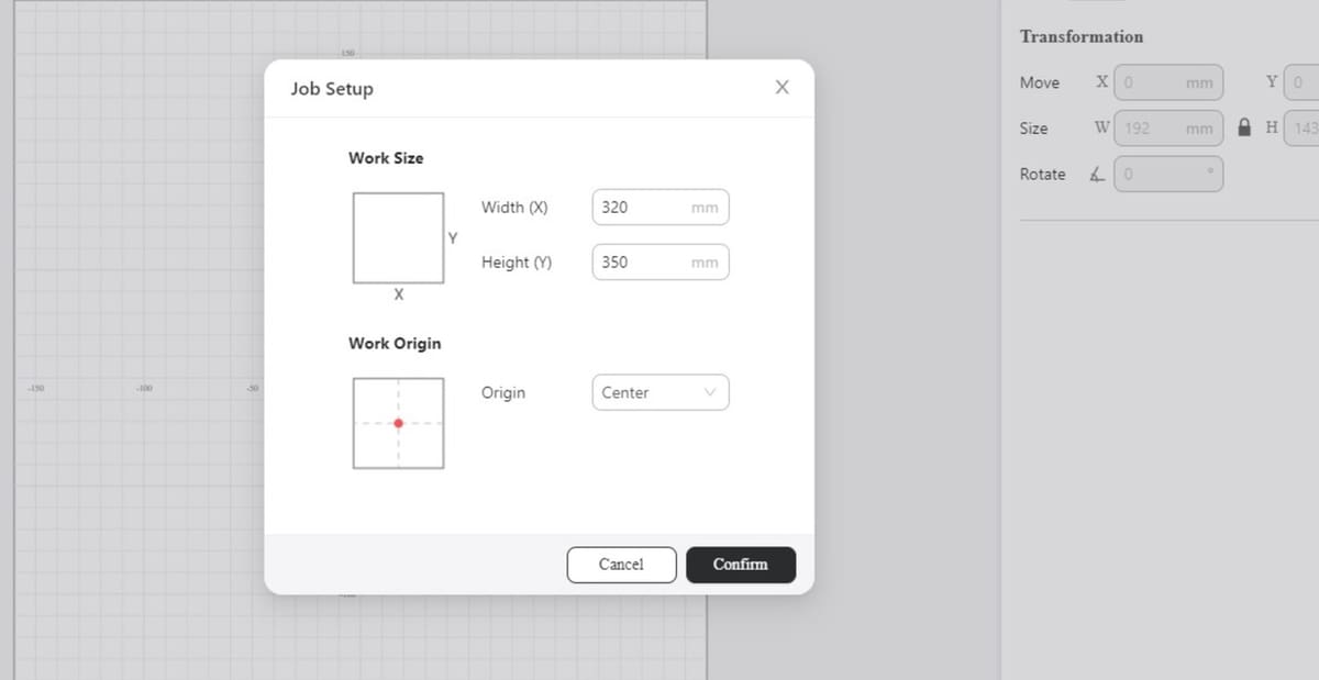
The first screen that we see is a pop-up window asking to confirm the dimensions and origin of the work area.
- Review the dimensions and make sure the “Work Size” dimensions are the same as your wooden sheet or change the numbers to your wooden sheet’s measurements. Then click “Confirm”.
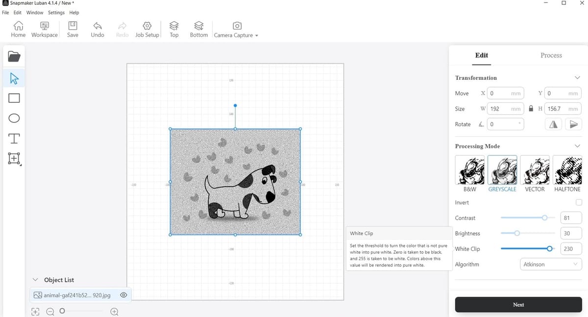
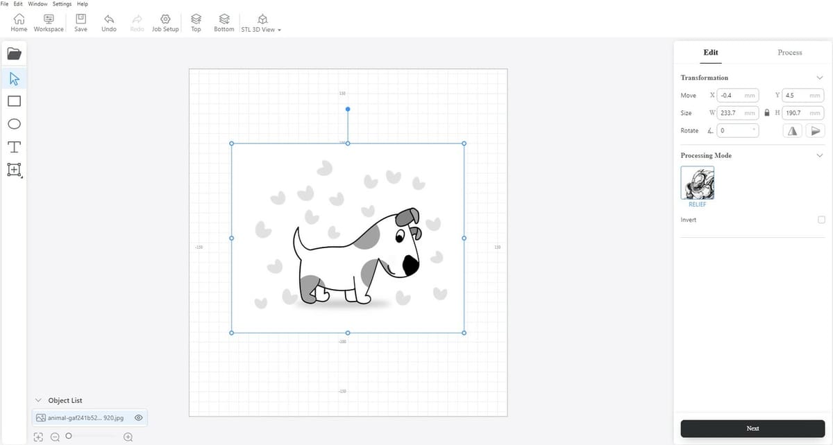
- Click the Import icon on the left toolbar (just like we did in the 3D printing tutorial, the folder icon), locate the non-vector image (the dog with hearts), and import it.
Processing Mode

Right away the program loads the image and converts it into grayscale. The four processing modes that can be seen are summarized as follows:
- B&W and Greyscale: These are basically two sides of the same coin, where B&W allows only two shades – 100% black or 100% white – while Greyscale allows different engraving “density” for the different shades of gray.
- Halftone: This is a method for engraving, which basically uses a lot of “small dots” to engrave the piece.
- Vector: This only reads “paths” from vector images, which is primarily used for cutting processes. It behaves similarly to what would be expected from a machine reading CAD software files, reading mostly lines, angles, and distances.
But we don’t see our little flying hearts anymore!
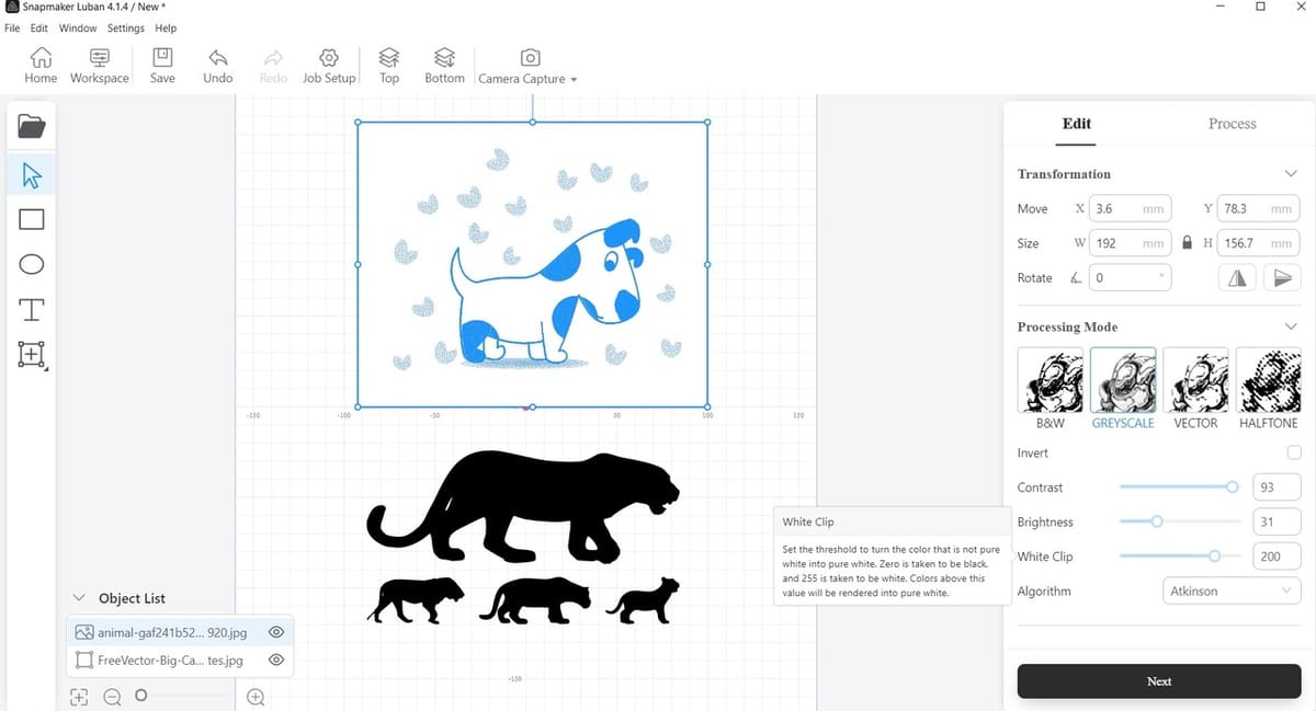
Non-vector Editing
Head to the Image Edit toolbar on the right. In the Processing Mode area, keep the Greyscale option since we intend to engrave this image. We also see five more settings:
- Invert: Inverts the black and white colors of the image.
- Contrast and Brightness: With these, you can tweak the contrast and the overall brightness of the image.
- White Clip: This setting sets a threshold to turn some of the light gray areas to pure white. This is used mainly to avoid engraving areas we don’t need in the image.
- Algorithm: Another setting that can be tweaked to get some slightly different variations in the processed grayscale image. It basically alters the way the computer sees and processes the black and white pixels in the image, their arrangement, and their density relative to each other.
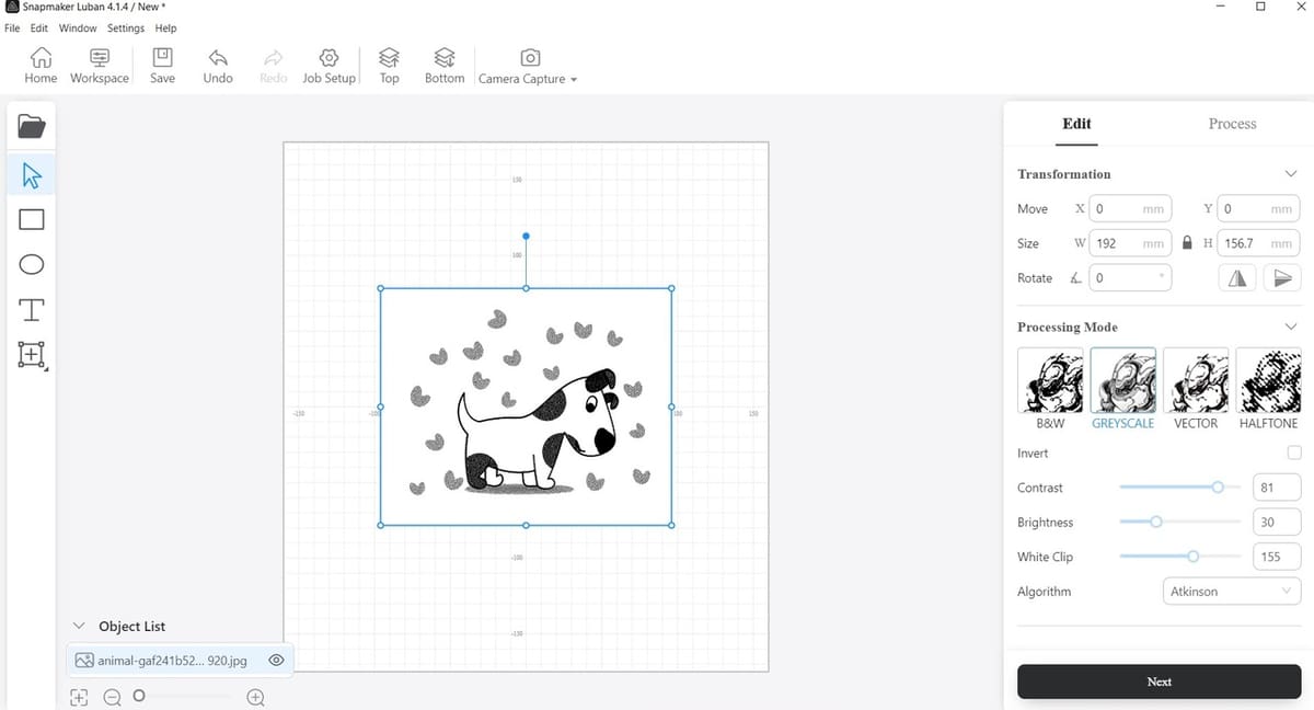
Tweak the image, mostly experimenting with White Clip and Brightness. We set the Contrast to 81, Brightness to 30, and White Clip to 155, which seemed to work for us for this particular example.
The final result is a nice simple grayscale image where most of the details we like appear to be present.
Importing a Vector Image
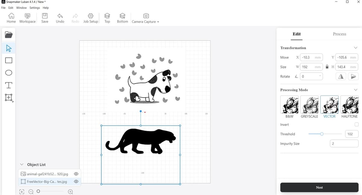
Next, import the vector image, then make sure that “Vector” is chosen on the Processing Mode toolbar to the right. This is important because this is what tells the machine to cut these lines in a set path.
Vector Editing
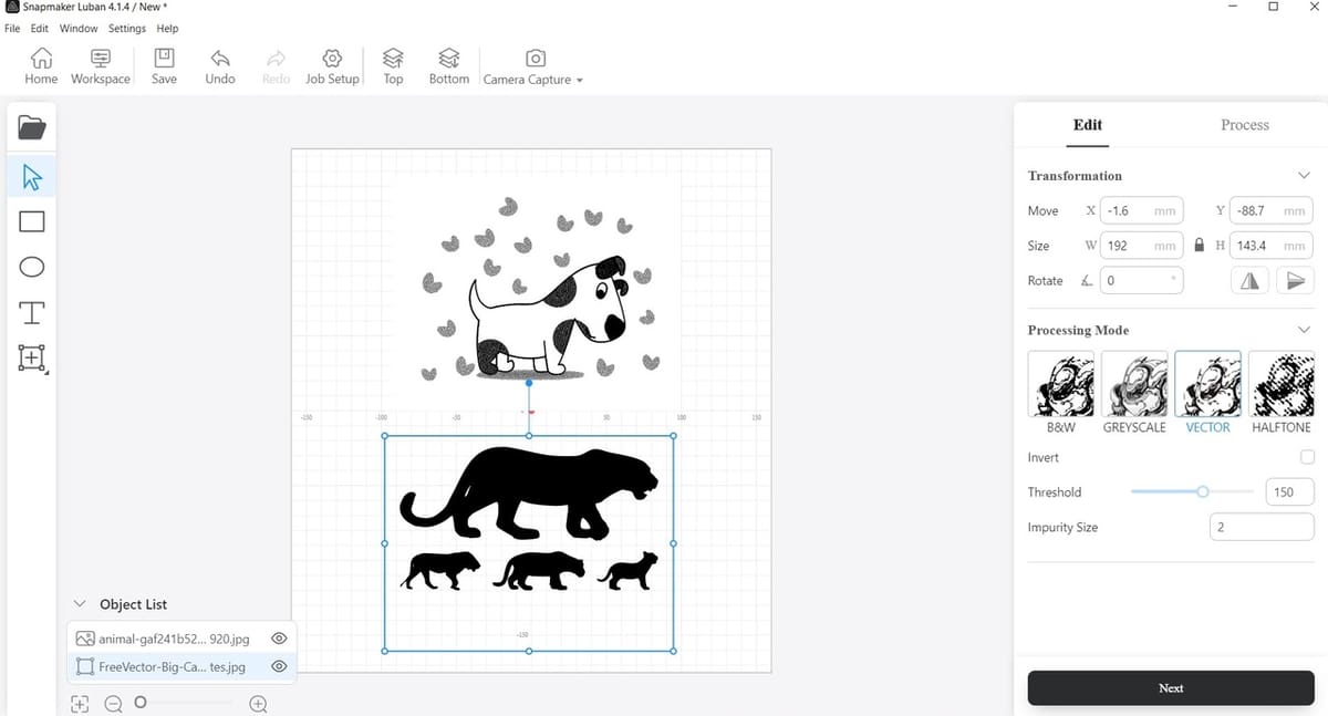
For the vector image, we also tweaked Threshold setting a bit until we could see the three smaller cats. As we want to fully cut the shapes of the big cat and the three smaller ones, for this particular example, we increased the threshold from 100 to 150.
A convenient feature of the software is that it keeps the settings for each of these two images separate, meaning that if we click back on the dog image, we can see it still keeps its grayscale settings. This is helpful because each image retains the parameters set specifically for it, so when you generate the G-code, it won’t use the same parameters for all the images, it will take into account all the modifications we made to each individual one.
Once all the settings are as wanted, click on “Next”, on the bottom right of the screen.
Creating Toolpaths
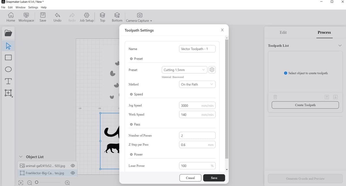
It’s time to create the toolpaths. For the cats, we chose the “Cutting” preset because we intend to fully remove the four little parts. For the dog, we decided to try the “Line-filled Engraving” preset. Both toolpaths have preset modes, which can be altered according to any specific needs.
- Make sure that the power and toolpath parameters are within the recommended range for your machine.
- There’s always the option to change the cutting or engraving parameters, and you can also save and export or import different presets. While engraving is a relatively simple process, every piece of wood is different, so some experimentation is needed if we decide to be picky with the details of the engraved piece.
- When you’re cutting, if too much power is used, the most likely issue will be that the wood will get a little burned or that it will get some stains on the edges, which can be cleaned off later. Some beginners may choose the maximum amount of power available to make sure that they get clean cuts (especially with thick wood), but for most applications this will result in your edges getting burned, so its best to stay moderate.
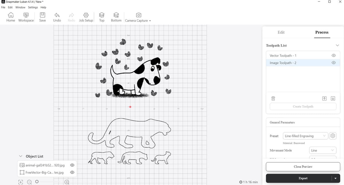
Generating the Laser G-code
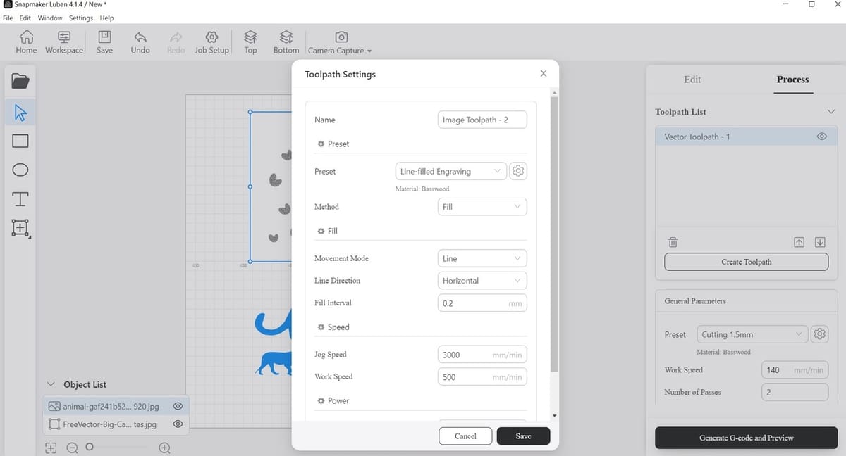
After creating the toolpath for each image, you’ll notice the images turn blue.
Once everything’s to your liking, click “Generate G-code and Preview” on the lower right.
Previewing
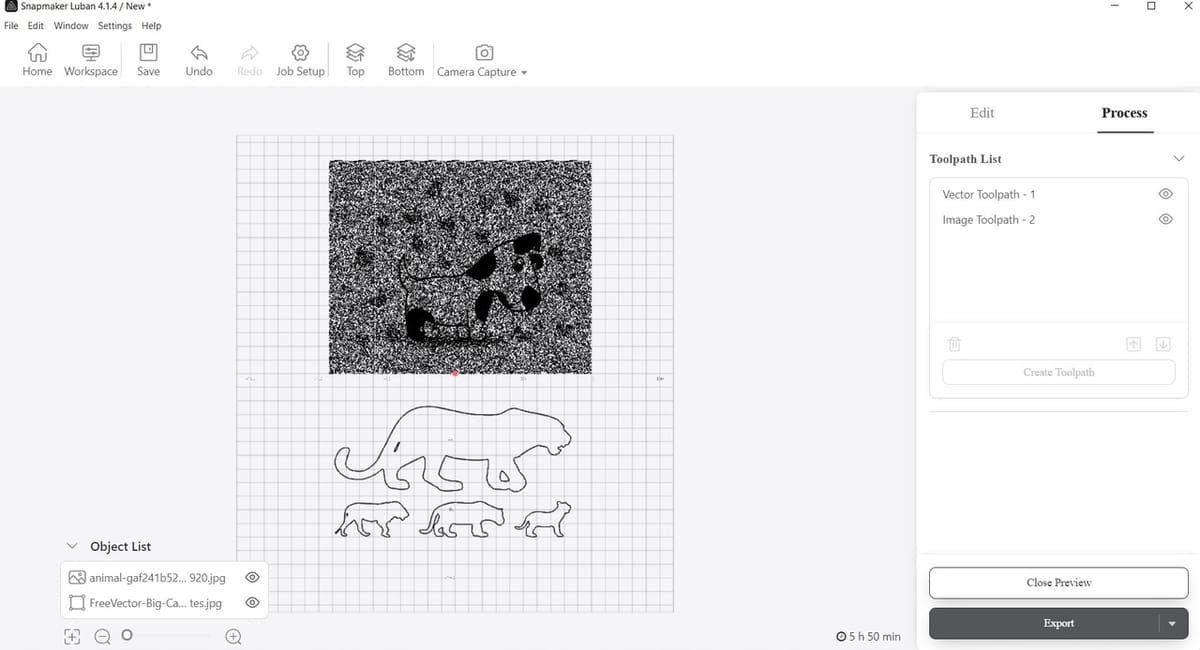
Woah! What’s that? The first image isn’t generated the way that we imagined it to be; it seems the program sees some tiny black spots in the white background. This means that we have to go back and edit it.
This happens sometimes, as it can be a trial-and-error process. Because each image is different, it’s always a case of continuously testing and reevaluating the parameters. Plus, little dark dots might not always be easy to see in the image but will appear more clearly when previewing the G-code.
Re-editing the Image
- To go back, close the Preview, select the corresponding toolpath, delete it by clicking on the trash bin logo that’s right below it or right-click on it and a drop-down menu will pop up; select “Delete”.
- Click on “Edit” (next to “Process” at the upper-right of the screen), confirm that the correct image is still selected (blue frame), and tweak the settings a little more to make sure that the white background is actually clear. Depending on the image chosen, any of the settings – Contrast, Brightness, and White Clip – might need to be altered.
- Create the toolpath for engraving one more time, and click “Generate G-code and Preview” again.
- Voilà! Everything seems to be in order, we can now export our G-code and begin cutting.
CNC Carving
Finally, if you’re interested in using Luban for CNC carving, you’ll be glad to know that it follows a very similar workflow to the laser section.
Importing Images & Processing Modes
Importing images works the same as in the previous workflow, however there are only two processing modes: “Relief” for carving, and “Vector” for mostly cutting operations. You can find these processing modes on the right, the same place you would find “Greyscale” and “B&W” in laser.
It’s also worth noting that you can import images or STL files (though some file types are restricted to only one processing mode). As we can see here, our dog image is restricted to only “Relief” mode because it isn’t the “vector” type of image.
Toolpath Settings
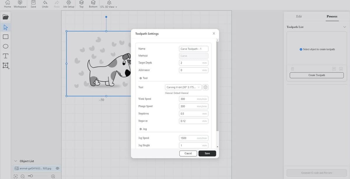
After importing and choosing our modes, we can create our toolpaths.
For the Toolpath Settings (see image), you’ll need to set the Target Depth, which describes how deep the carving is going to be. Allowance can be left at zero for most applications, as it’s a setting that’s used to describe the amount of material remaining on the object that needs to be carved
For the Tool section in the Toolpath Settings window, you can choose to change the Work Speed (the speed at which the tool moves when it’s carving) and Plunge Speed (the speed at which the tool “carves” into the material). The “Jog” section mainly deals with the speed at which the tool moves while not carving.
The default values will suffice unless special circumstances dictate otherwise. Then, G-code is generated the same way you’d do it for laser engraving or cutting.
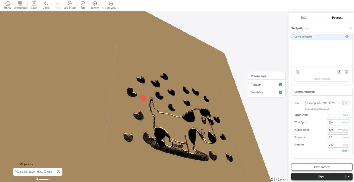
At this stage, you can choose to simulate the results. The simulation window shows the shape of the wooden piece after the carving operations are done. It’s a nice option for clarification purposes.
While CNC operations usually involve lots of parameters and a lot of tweaking, the software optimizes the process nicely for simple projects such as carving our dog photo on a piece of wood using an end mill instead of a laser.
It’s worth noting, however, that this particular feature is slightly limited compared to other engineering software usually used with CNC machines. If advanced control of CNC milling operations is needed, more complex CAM software is usually employed. The target audience of this particular feature are hobbyists and machining beginners, so everything is simplified and made to be as concise as possible.
Conclusion
Snapmaker is a really great tool for those looking to get into 3D printing or wood cutting and engraving. For anyone interesting in laser especially, this will be a great addition to your software collection. The process is very straightforward and simple, yet it allows for room to experiment and tweak the various processes’ parameters.
One more thing to note: If you feel adventurous, there’s always the option of changing the configuration files of the 3D printer, laser, and CNC presets.
The path for most of these configuration files (in JSON format) is:
\Snapmaker\resources\app\resources\CuraEngine\Config\
Proceed with caution and plenty of backing up, though, because this is basically the bread and butter of the software. Note that, for 3D printers, the default material diameter is 1.75 mm filament since that’s what the Snapmaker machines support. If you’re not using 1.75 mm filament and want to change the diameter of the filament you’re using, just export the Material Settings preset and change the material diameter value in the JSON file using a text editor. Then, import it back into the software.
Additionally, if you ever find yourself in need of further resources, there are several options. The Case Library shown on the Home screen is good for getting used to the software and testing the various options. The Case Library basically contains some models to show the program’s different capabilities. You can also find official YouTube tutorials, as well as support on the Snapmaker forum and on Reddit.
Happy crafting!
License: The text of "Snapmaker Luban Software: How to Get Started" by All3DP is licensed under a Creative Commons Attribution 4.0 International License.