Surface Modeling (CAD) – Simply Explained

Solid modeling -- manipulating and combining blocks -- can only take you so far. This article explains what surface modeling is, exploring the benefits it delivers compared to solid modeling.
Surface vs Solid Modeling
Every 3D CAD modeling process begins with a 2D sketch. From that sketch, there are two main options to bring it into 3D: solid extrusion or surface geometry. The results can sometimes be the same, depending on what you want to achieve.
In this article, we’ll show what surfacing modeling is by comparing it to solid modeling. Specifically, we’ll look at two models created using both techniques. The software used to demonstrate the differences is Geomagic Design X.
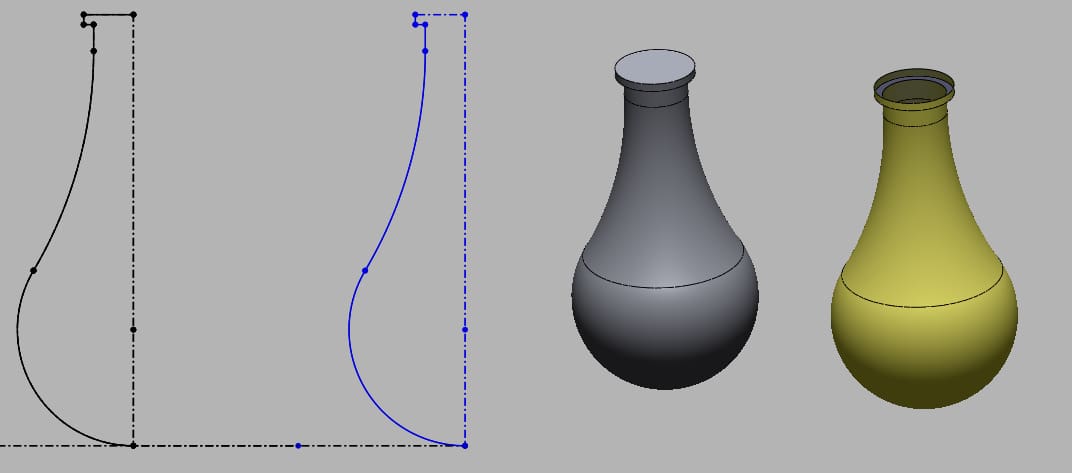
In the first example, the same model — a bottle — is made with both surface and solid modeling. Both methods begin with a sketch that is almost exactly the same, minus the top surface in the surface model. Next, the revolve feature is used, where the first model is revolved with solid geometry and the second with surface geometry.
1.1. Defining the Shell of the Bottle
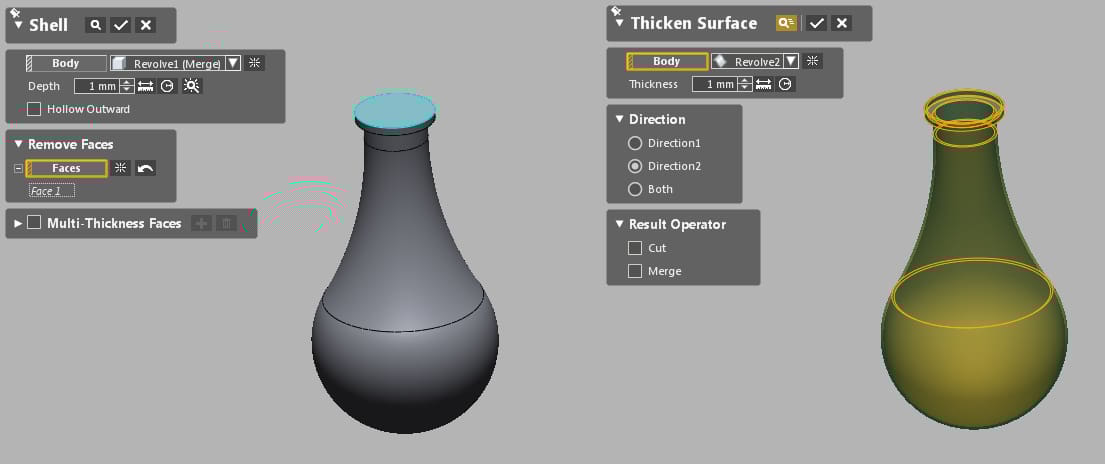
For the solid model, the “shell” feature is used. The model (including its upper surface) is selected to define the open part of the model. The thickness of the shell is 1 mm.
For the surface model, the thicken feature is used with a thickness of 1 mm. As you might expect, the result is that the surface has a thickness of 1 mm.
1.2. The Result
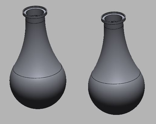
As you can see from the picture, the two finished parts are the same, even though two different modeling techniques were used. Normally, in every 3D CAD modeling job, you need to select the best modeling technique in order to be fast and efficient. In this case, however, the decision didn’t really matter because the revolve feature was used.
Still, one can see that the two techniques focused on different aspects. Whereas the shell feature defined a 3D shape with a particular thickness, the thicken feature simply “enhanced” a 2D curve.
2.1. Solid and Surface Modeling Combined
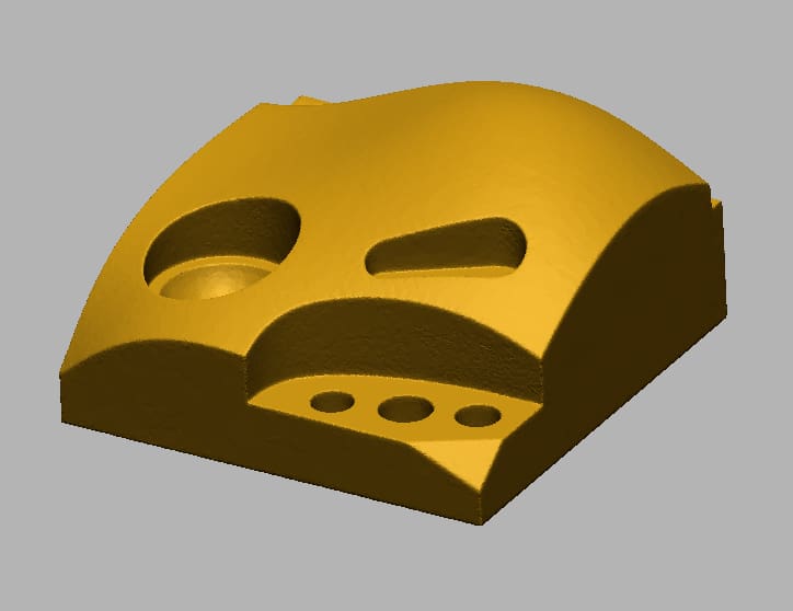
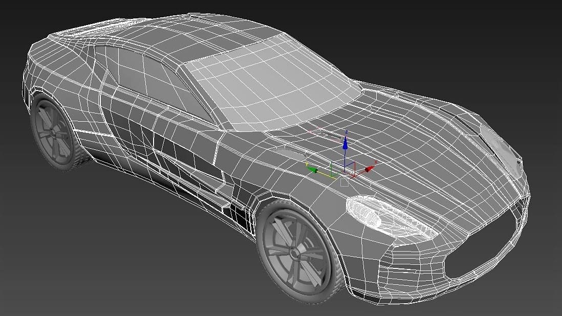
Some models are impossible to define using only solid features. Sometimes you need to integrate surface features in order to define the complete geometry. The example model in the image has an upper surface that is organic in its geometry and can’t be modeled with solid features. Let’s see how this is done.
2.2. Defining Solid and Surface Parts
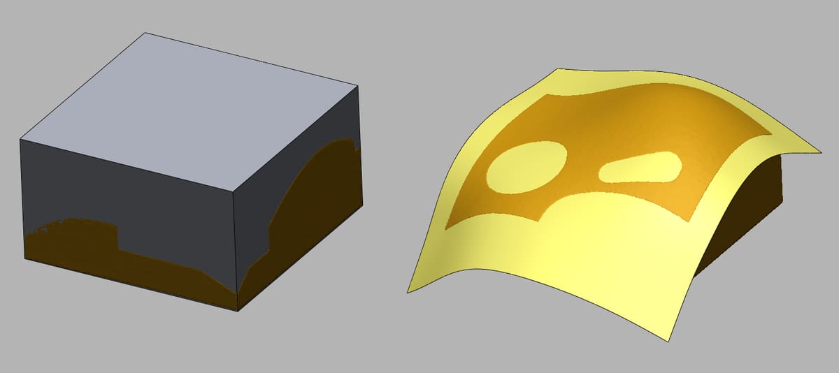
The base of the model is simply defined using the extrude feature, the most common solid modeling operation. In effect, a rectangular prism is “grown” out of a 2D rectangle.
In contrast, the upper surface is generated using the “mesh fit” feature, a surface modeling operation. Essentially, this means that a particular 2D shape (a mesh) is automatically applied to a particular surface.
With these two components prepared, one can move on to the next step.
2.3. Combining Solid and Surface Parts
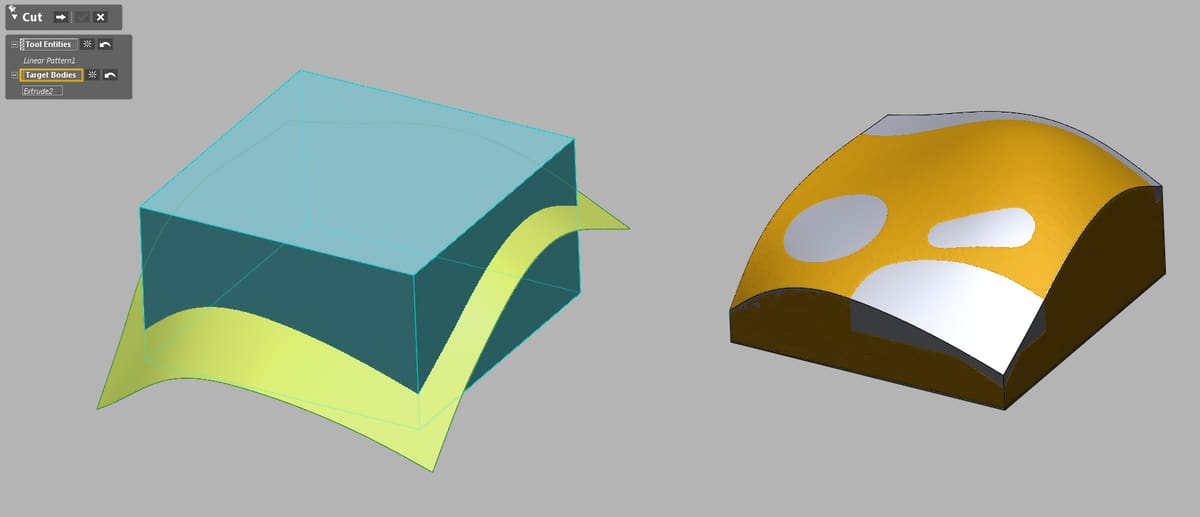
Putting the solid and surface parts together is done using the “cut” feature. By perfectly cutting the solid model, the surface model produces the upper part of the result.
Using the same two steps, the rest of the model is generated, including elevations, holes, and protrusions.
2.4 The Result
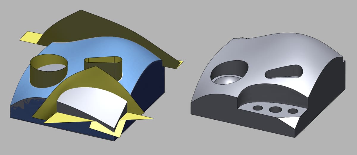
From the final result, one can see that, without surface modeling, it would be impossible to 3D model this particular part. (Or, at least, it would be very very difficult.) With knowledge of both modeling techniques, there’s no model you can’t create.
Conclusion
If the part allows it, sometimes it’s possible to produce a model using only solid or surface modeling. But certain pieces, especially ones customized to unique practical applications, will require both.
We hope this guide was able to demonstrate that solid and surface modeling are not two separate techniques, but two areas of techniques. The former is useful for manipulating common 3D shapes, while the latter focuses on the customization of specialized surfaces (even if later they’re extended or applied to a 3D shape).
Ready to get to work? For the right tool, check out our list of the best free CAD software tools of 2018.
License: The text of "Surface Modeling (CAD) – Simply Explained" by All3DP Pro is licensed under a Creative Commons Attribution 4.0 International License.