The 3 Main Types of 3D Modeling – Simply Explained

Various types of 3D modeling allow us to design various things, some better than others. Read on to see the best type of 3D modeling for you!
When making a 3D representation of something, be it for manufacturing or just for animation and rendering, you’ll need to make a 3D file, such as an STL. These files are basically massive lists of coordinate points that define a shape. However, it would be very difficult for a human to go about designing something in 3D by only declaring coordinates.
For that purpose, CAD software was invented. These programs allow designers to create coherent dimensions and designs by means of a visual interface. The program takes care of all the calculations and creates the file with all coordinates, so the designer only has to worry about shapes and sizes.

But not all CAD programs are made equal. That’s not to say that some are better than others (although that’s also true), rather that some approach modeling in different ways than others. And that’s what we’re going to look at in this article.
Types of Modeling
Within CAD, there are three main types of 3D modeling – solid, wireframe, and surface – and each has its own advantages and disadvantages. Of course, there are other types, but most exist either as a subset of these three or are highly specialized for their specific purposes.
- Solid modeling works with three-dimensional shapes. The shapes may vary, but they act together like building blocks. Some of these blocks add material while others subtract, depending on the input. Some programs can use modifiers, working with the solids as if you were physically milling it in a workshop. Solid modeling is fairly straightforward both for users and in terms of computer power.
- Wireframe modeling can help in cases where the surface is complex and curved. Eventually, you’ll find that the basic building blocks of solid modeling are too obtuse for some applications, and wireframe modeling provides the finesse for more complex forms. However, as complexity rises, some drawbacks emerge.
- Surface modeling is the next step up in complexity. Highly professional applications demand smooth surfaces and seamless integration, and this can be handled by more advanced programs that require more work and computing power. However, here you can achieve shapes that would be nearly unattainable with the other two methods.
Let’s take a deeper look at each one of these methods, along with their individual pros and cons.
Solid Modeling
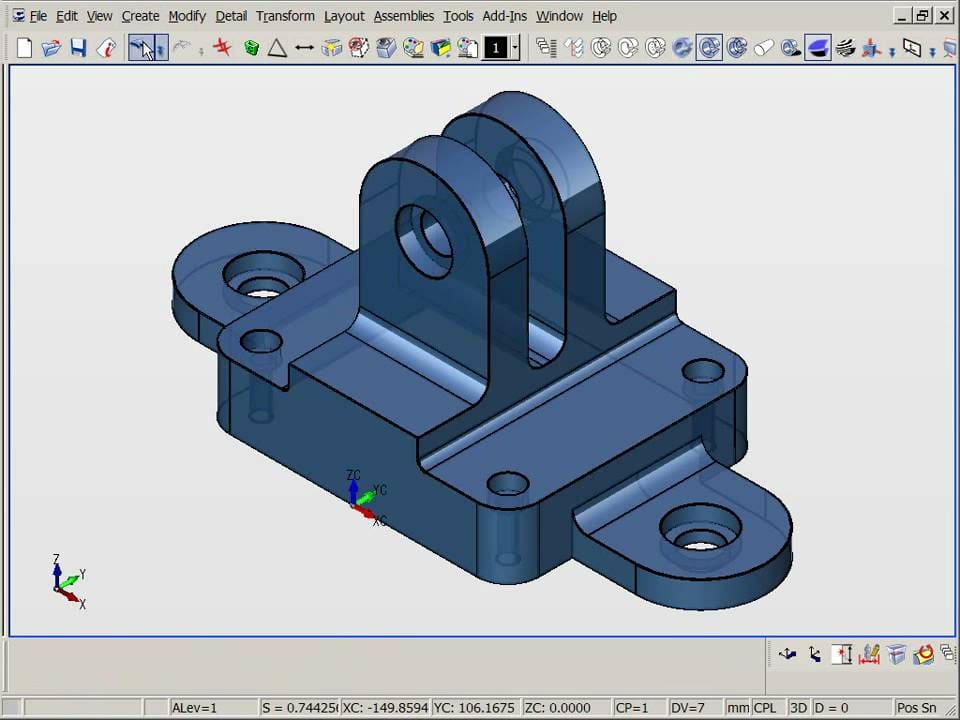
Solid modeling involves working with primitive shapes, such as spheres, cubes, and n-sided prisms. Yet, different programs may use different procedures. Some start with two-dimensional sketches that are then extruded to produce a three-dimensional figure. Others add solid over solid in order to produce more complex figures. But the end result is the same.
This kind of modeling is especially useful when flat surfaces or simple curves of constant radii are involved. It also lends itself quite well to precise dimensions and angles. Think of mechanical elements, machines, and basic representations of natural things.
Some notable pieces of software that employ solid modeling include Tinkercad and FreeCAD at the entry-level, and for more advanced work, SketchUp, SolidWorks, and Fusion 360.
Advantages
- Tools are easy to understand and work with; the user doesn’t require extensive training.
- Computational requirements are lower since the computer isn’t working with thousands of triangles.
- The final pieces are always mathematically correct in the sense that the model is possible in the real world.
Disadvantage
- High realism in the representation of organic shapes is almost impossible to achieve.
Wireframe Modeling
Looking at the real world, one quickly perceives that reality is somehow more than a cumulus of cubes and spheres. People, animals and plants have complex shapes. If your aim is to achieve a semblance of realism, you’ll need another technique – something more advanced than solid modeling.
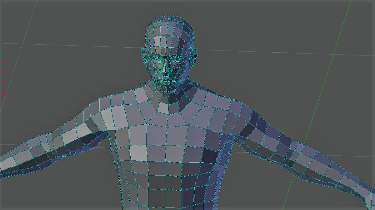
Wireframe modeling represents shapes as a network of vertices. Each geometric face is composed of at least three vertices, and each vertex can be part of one or more faces. The size and shape of things are modified by changing the position of each vertex.
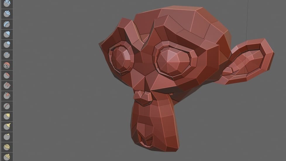
Many wireframe modeling tools use triangles as their basic elements, and the more triangles use, the higher the realism. This is indicated by “polygon count”, the total number of triangles (or other planar shapes) contained within the wireframe of a model.
Historically, this technique was the first to be used to model 3D figures, then having relatively low polygon counts, making figures somewhat blocky. Nowadays, it’s not uncommon for shapes to reach millions of polygons. This might not be a problem when software is locally run, but for web-based software, this can cause severe lag. In some cases, there’s even a limit on the number of polygons that can be used.
There are many programs that use this approach, but some of the main programs that allow for the individual manipulation of wireframe vertices are Blender, Maya, and Daz 3D.
Advantage
- It’s possible to achieve more complex surfaces and curves compared to solid modeling.
Disadvantages
- Users require more training.
- High resolution will require millions of polygons and computational needs will be higher.
Surface Modeling
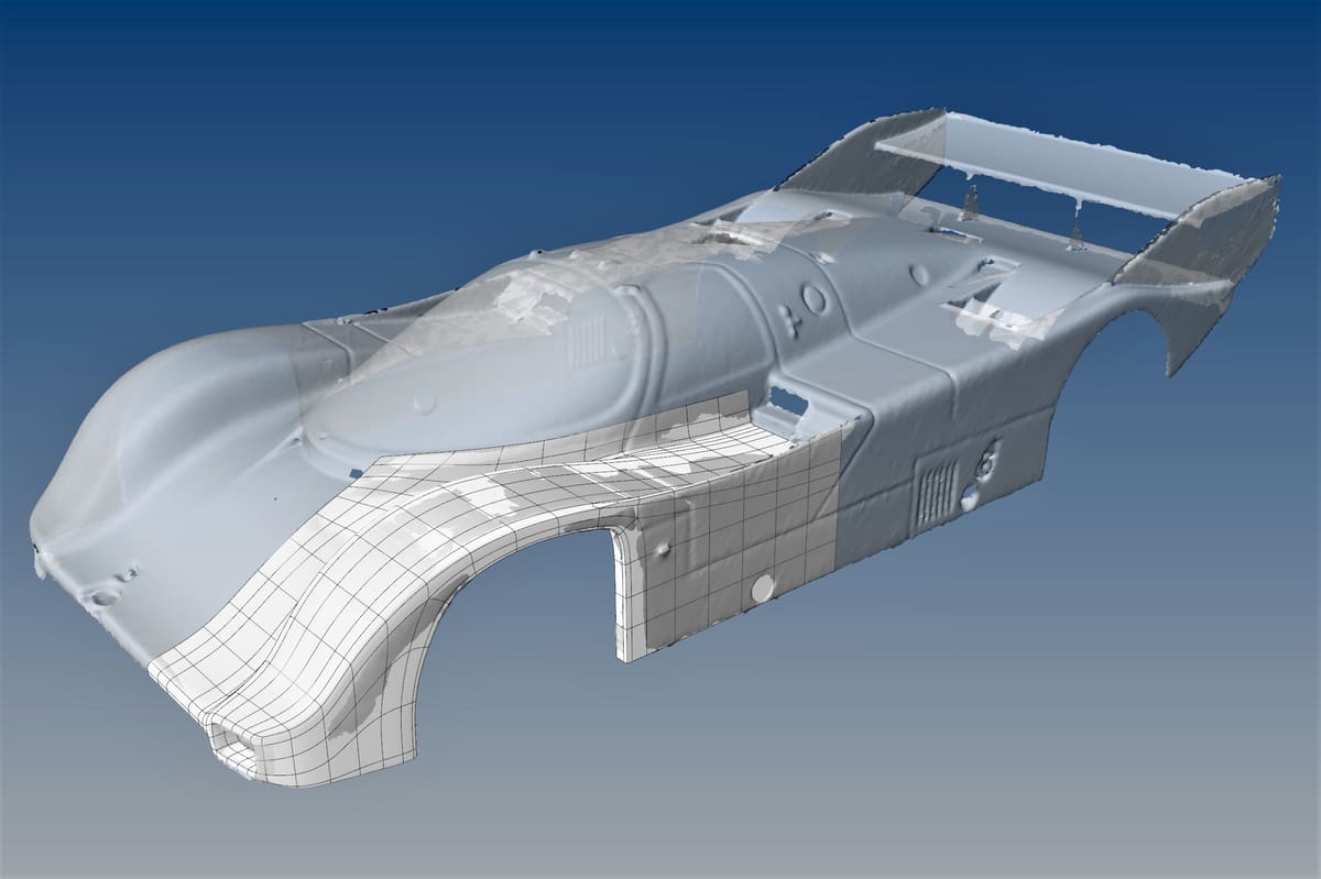
The most advanced of these three techniques is surface modeling. It relies on guiding lines to define the shape and curvature of a part. The software then calculates a smooth surface that connects the guiding lines.
This way of working imitates the way airplanes and boats are made: Think of the guiding lines as the internal ribs of an airplane structure, the surface is the metal skin.
The aforementioned example is the exact reason why this process was devised. In aerodynamic and thermodynamic designs, the behavior of the flow around solid shapes is of utmost importance, and the shape of the silhouette will determine if an element is effective or not. Since the seamless integration of all elements is necessary, surface modeling is the best way to approach these challenges.
The use of guiding lines is not the only option. Some programs use control points or control planes, where the desired surface follows the planes tangentially. The caveat is that, since this way of working focuses so much on surfaces, it can produce visual representations that are not possible in the real world and are therefore impossible to make. Before manufacturing, it’s necessary to ensure that the design is physically possible, or “manifold“.
No program is dedicated uniquely to this technique, this is just another tool in their box. Yet, its underlying principles are so distinct that it’s considered as a unique modeling technique. In many programs, the main tool that does this job is called “Loft”. Some of the programs that can handle this type of modeling are Catia, FreeCAD, Inventor, and SolidWorks.
Advantage
- It’s possible to produce complex surfaces. This is convenient where appearance is important, such as in the automotive industry, or where fluids are involved, such as in aircraft or thermodynamics.
Disadvantages
- This technique is more complex and requires more advanced programs.
- More advanced programs will demand far more training and experience from the designer.
(Lead image source: evanf via Blender Stack Exchange)
License: The text of "The 3 Main Types of 3D Modeling – Simply Explained" by All3DP is licensed under a Creative Commons Attribution 4.0 International License.