![Featured image of [Project] 3D Printer Bed Leveling Tool](https://i.stageall3dp.com/workers/images/fit=scale-down,w=1200,h=675,quality=79,gravity=0.5x0.5,format=auto/wp-content/uploads/2019/02/08072702/3d-printed-led-bed-leveler-techkiwigadgets-instructables-190207.jpg)
[Project] 3D Printer Bed Leveling Tool

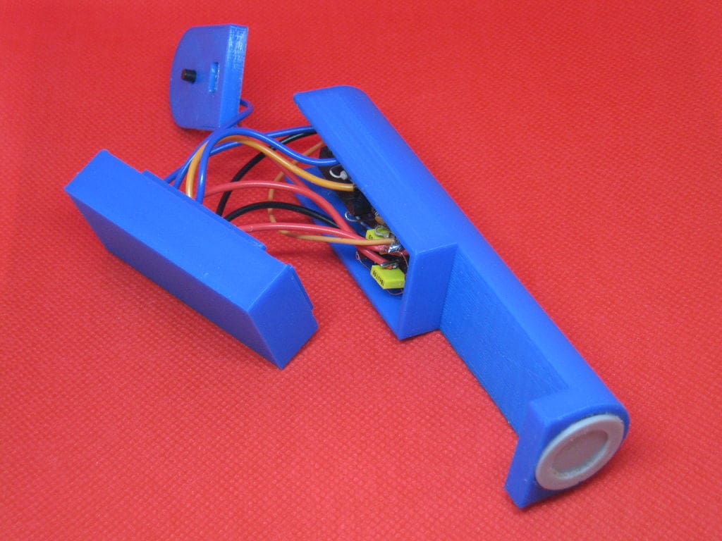
TechKiwiGadgets teaches us how to make a 3D printed LED bed leveler that uses a DIY sensor and a LED bar graph to tell the relative distance between the print bed and the extruder.
DIY Leveler
Not all 3D printers have auto bed-leveling, and for those that don’t, it can be irritating when you have to adjust things manually after every few prints. A majority of budget machines on the market don’t come with this helpful tool, and buying one to add yourself can cost a pretty penny.
This prompted TechKiwiGadgets to come up with a 3D printed LED bed leveling device that relies on a sensor and a LED bar graph to measure the relative distance between the sensor and the extruder.
This add-on does not require any code alterations to your firmware or any special wiring. You can simply attach it to your printer whenever you want to tune the bed level. And then, voila, you can remove it when you are done with the bed leveling process.
Note: This particular unit is measured for the Creality Ender 3 printer, but it can be altered for other printers. TechKiwiGadgets insists that a metal print bed is a prerequisite before using this tool
How it Works
This LED-based bed leveler uses a pulse induction sensor coil that is powered by an Arduino Nano. The sensor coil has separate RX and TX coil so that when a pulse is induced into the TX coil, an electromagnetic field is created around the RX coil. A voltage is then induced into the RX coil as a result of the changing field. This voltage is detected and intensified before the PCB board reads the pulse width signal.
In the Arduino code, a smoothing algorithm is used to eliminate the noise from pulses. In addition, the code also has a calibration algorithm that takes the average of readings over a short time after the tool is switched on. This algorithm sets a threshold to compare the signal against.
Whenever a metallic surface/object comes close to the electromagnetic field, this field gets disrupted, and some of this energy is diverted into “eddy currents” that form in the metallic surface/object. This effect results in the pulse width – detected in the RX coil – reducing. In a nutshell, you will be measuring the loss of power into the metallic surface.
Another algorithm translates the pulse width variation into an LED bar graph to indicate the relative distance between the bed and the coil.
The calibration button is used to reset the baseline height and to re-center the LED indicator to the center of the bar graph.
What You Need
Main Components:
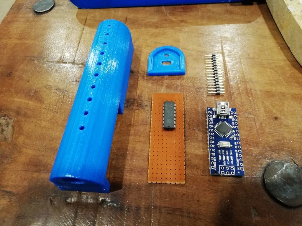
- Arduino Nano (comes with a USB connector and pins pre-mounted)
- 10x LED Pixel light
- MOSFET N-CHANNEL
- Transistor
- Voltage Comparator
- Ceramic capacitor (150pF)
- Capacitor (18nF)
- Capacitor (10nF)
- Mini Tact Tactile Push Button Switch (6mm)
- Power bank
- Vero Board (you will have to cut this board if you want it to fit inside your printed part. You only need 21×7 holes)
- Resistors
- Wire Kit
- Breadboard
- Enameled Copper Wire (0.3mm diameter)
Extras:
- Hot glue
3D Printing the Case
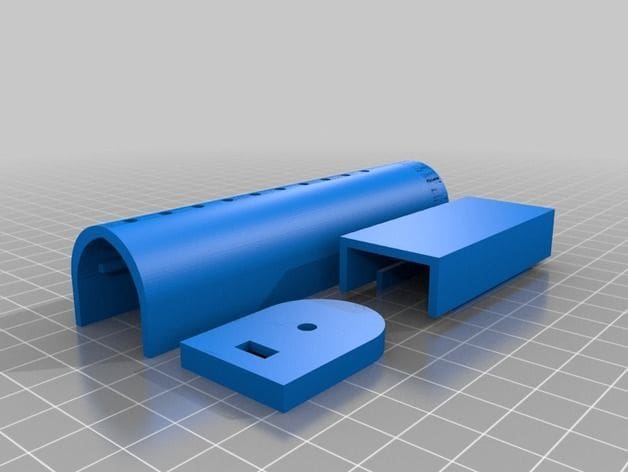
The 3D files are available on Thingiverse courtesy of TechKiwiGadgets.
Print settings:
- 100% infill
- 0.2mm layer resolution,
- Raft: yes
- Supports: yes
Sensor Coil
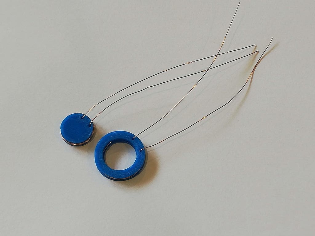
Wind twenty turns of the copper wire on the inside and outside coil formers; making sure there is an extra 15cm of wire left that will be connected to the circuit board. Each former has two holes; one will be for the entry and another for the exit.
Fasten the coils into place using hot glue to prevent them from unwinding then push the two coils into each other until they join, but leave the four wires oriented in one direction.
Thread these wires through the wire guides of the main 3D printed body. You must know where each wire is coming from before connecting to the circuit board later. Push the conjoined coils into the opening of the 3D printed unit, but don’t glue the head first because you will need to add LEDs.
The Circuit
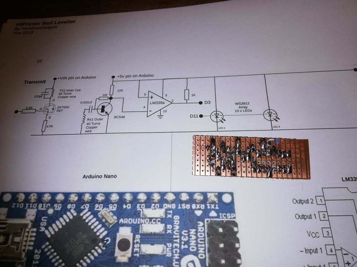
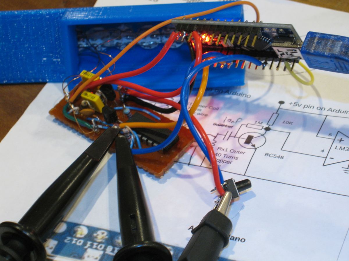
TechKiwiGadgets recommends testing the circuit with a breadboard. Testing is a great way of confirming that your components are well connected and the coil is wound as required. You can then transfer the set up to the Vero board.
For troubleshooting purposes, TechKiwiGadgets has provided an image of the Oscilloscope traces on Instructables.
Once you have ascertained that your connections are right, follow these steps:
- Connect the Arduino Nano to the Vero Board using header pins
- The positioning of the PCB and the Vero board is essential. The two should be oriented as per the guides in the printed part. You can then use hot glue to fasten them
- The ten WS2812 LEDs will be used to make the bar graph. The LEDs are connected with wires and then glued to the printed part before they are aligned to the openings of the printed part
You are now ready to test your circuit before you attach the coils.
Assembly
The coils will be connected to the Arduino, which you will connect to a computer to load the code. The code needed for this tool is available on TechKiwiGadgets’ Instructables project page.
First, add “FastLED.h” to control the LEDs then initiate the IDE function to test your setup. This circuit should give you around 480uS.
Note: The coils have a polarity that will likely affect performance. Therefore, if you experience issues, TechKiwiGadgets recommends reversing the polarity of either coil.
Breadboard testing will give a lower output when compared to the finished unit. TechKiwiGadgest suspects that this is as a result of lost capacitance caused by the 3D housing. But this should not be a major concern
Once you have conducted all the tests, you can now put the leveler on your printer to figure out how it works exactly.
Testing on a 3D Printer
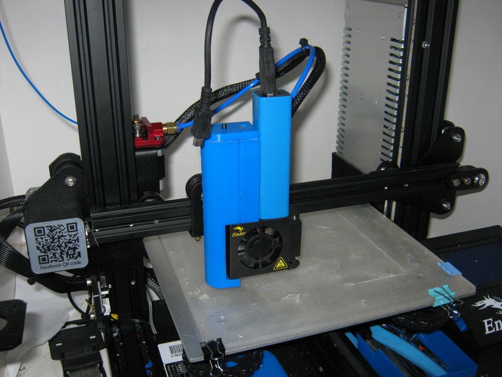
After finishing the assembly, TechKiwiGadgets tested this bed leveling unit on an Ender 3.
Here are the testing steps:
- Attach the tool to the extruder and connect it to the power bank. The LEDs should indicate that a power source has been connected
- Manually adjust the Z axis down until you hear a clicking sound from the microswitch
- Gently press down the calibrate button. This should be done gently to prevent the carriage from moving. Once calibrated, the LED will be around the center
- Move the print head across the print bed to establish the relative height between the coil and the extruder. If you notice that the LED is lower than the reference point, it means the print bed is a bit lower and needs to be moved The LED will move to the required height when you start adjusting the print bed
- To validate your heights, you can perform some test prints
Your 3D printer bed leveler is now ready to be used whenever you want to level your bed!
License: The text of " 3D Printer Bed Leveling Tool" by All3DP is licensed under a Creative Commons Attribution 4.0 International License.