![Featured image of [Project] Auto-Correcting Analog Clock](https://i.stageall3dp.com/workers/images/fit=scale-down,w=1200,h=675,quality=79,gravity=0.5x0.5,format=auto/wp-content/uploads/2018/12/03163906/gzumwalt-instructables-181203.jpg)
[Project] Auto-Correcting Analog Clock

In this Weekend Project, we build an "old" analog clock, designed by Instructables user gzumwalt. The 3D printed gadget corrects itself via software and an NTP clock server.
Analog Through Digital
This “antique” auto-correcting analog clock was designed by Instructables user gzumwalt. Rest assured, it’s the real thing (kind of). That’s because the inspiration for the original design came from a real analog belonging to gzumwalt’s grandmother.
This DIY clock takes after grandma’s in a number of ways. For example, assuming you follow the instructions to the T, the case should be printed using wood and copper PLA. Apart from that, all of the inner workings are just like those found in grandma’s clock.
Naturally, there are some major differences, as well. While the former clock used a spring-driven mechanism, gzumwalt’s uses an Adafruit Feather ESP32 and a stepper motor.
How the Clock Works
This auto-correcting clock relies on software and an NTP clock server to keep time.
At regular intervals, the software will poll the NTP clock server, and the time received – from the NTP server – is recorded in the ESP32 clock. Whenever it’s 12:00 (either noon or midnight) and the clock happens to be off for any reason, the software will fast-forward the hands to the 12 o’clock position, from which point the clock will resume its operation.
What You Need
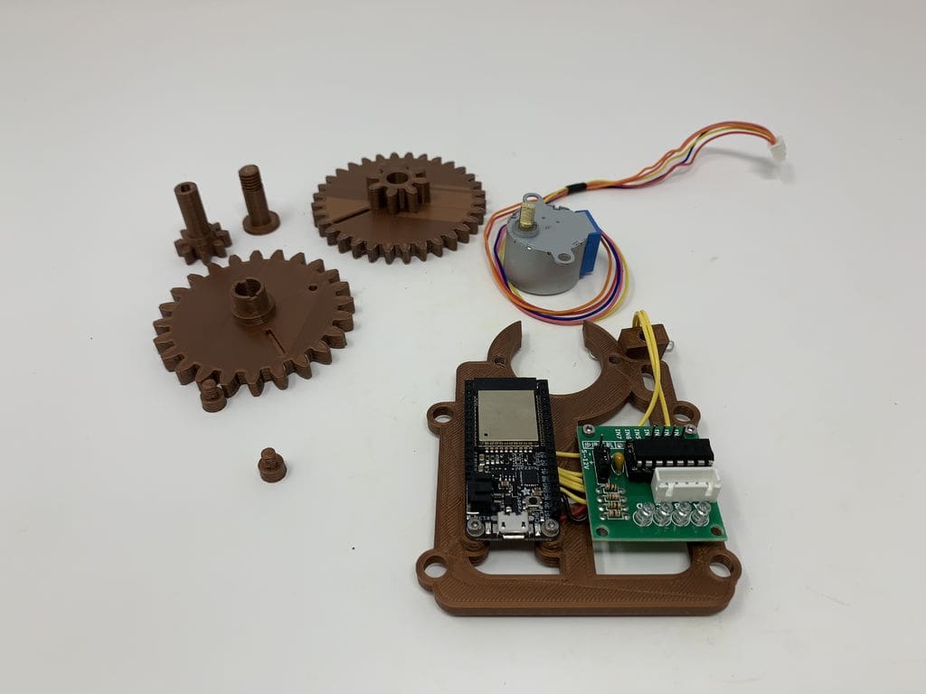
Main Components:
- Adafruit Feather ESP32
- Adafruit “slim” female socket headers for the Feather ESP32
- Adafruit lithium battery (3.7 V, 1200 mAh)
- USB to ESP32 USB cable
- Stepper motor, cables, and controller
- Reed switch (10 pieces in the pack)
Hardware Supplies:
Printing:
All the STL files are available on the Instructables page.
Using an Ultimaker 2 Extended+ and an Ultimaker 3 Extended, gzumwalt 3D printed all parts using a layer height of .15 mm and didn’t require any supports. Most of the pieces were printed using a 20% infill. Bolts and standoffs were printed using 50% infill.
The DIYer designed the parts in Autodesk Fusion 360 and sliced them using Cura 3.5.1.
Assembly
Before assembling the printed parts, test if they fit and file or sand them as much as you can to facilitate a smoother movement. Ensure all the edges that were in contact with the printer plate are well filed.
Pay special attention to moving surfaces, like the gear teeth, and eliminate any build plate “dirt”. For the threaded parts, a tap and die set may come handy, mainly because this clock relies on threaded components.
Once you’ve done those things, here is a general overview of the assembly steps:
- The Reed switch goes into its 3D printed holder. This component is fragile and needs to be handled with great care. For example, only bend reed switch wires using quality pliers to reduce the probability of breaking.
- Adafruit demonstrates how to assemble their Feather Board using socket connectors.
- Wire the Adafruit Feather Board to the reed switch and the stepper motor controller. You’ll be soldering while also using screws and nuts to join these three components.
- Most importantly, you need to know which wires go where when soldering, as you can’t afford to mix up the polarities. Remember, the Adafruit Feather Board and the stepper motor controller will be attached to the side that will not accommodate the gears. Hold the components in place using screws and nuts.
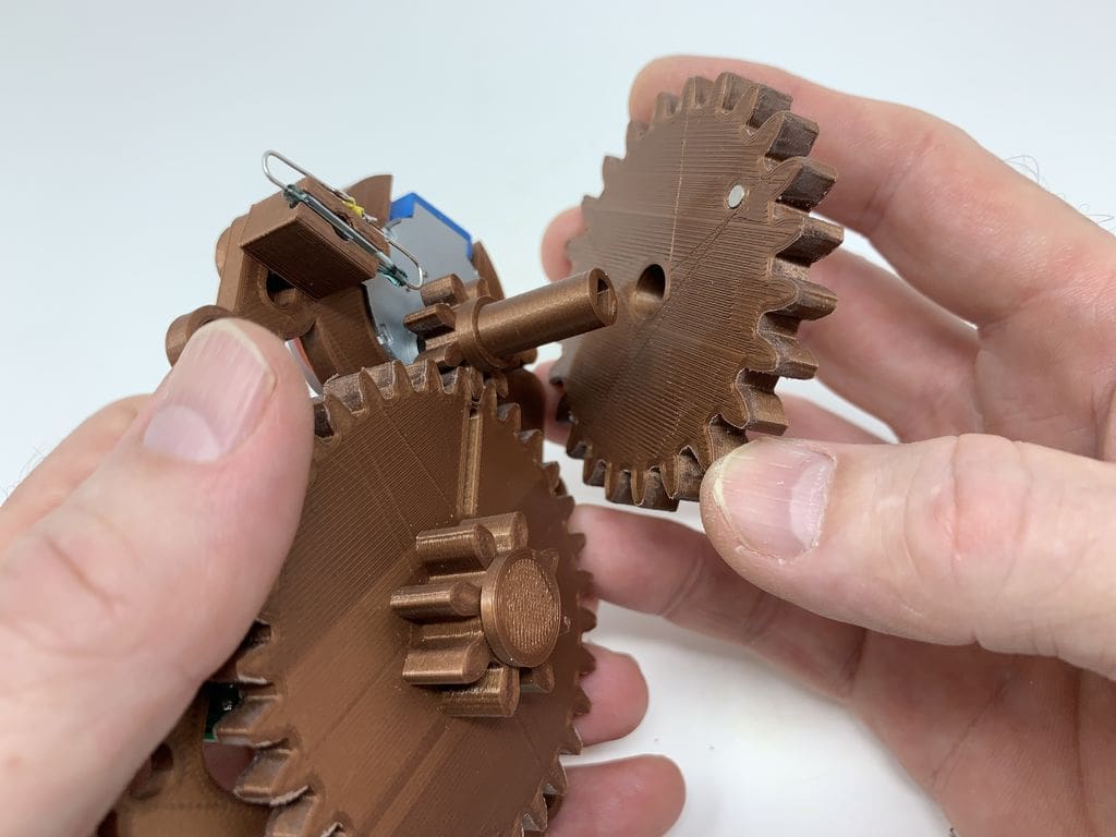
- Press the 3D printed gear on the motor’s shaft. Place another 3D printed gear on the assembled frame – in the proper orientation – and secure it with a 3D printed axle gear.
- Press three of the magnets firmly on one side of “Gear, Hours.stl”. Position the reed switch assembly in the appropriate place and secure it with a 3D printed bolt.
- Plug the motor connector into the controller board after wrapping any excess wires around the motor.
- With the slots aligned, place your hour gear assembly onto the other gear. Once done, all the gear slots need to be in a vertical position. This is your clock’s 12:00 position.
- Its test O’clock. Power up your boards using either USB or battery and load the “Clock.ino” file. You’ll have to tweak the source codes, as shown in Step 5, before you can download the code. Once the code is ready, the minute gear should make a 90-degree counter-clockwise rotation before turning clockwise. After that, the reed switch will be activated.
- The clock should halt at 12:00. If it fails to do so, there are certain things that you need to adjust as per Step 5. Otherwise, if the clock makes a stop at 12:00, you’re good to go
- “Lock” the reed switch holder with some glue.
- The final part of this step involves changing the source code and downloading it before removing power.
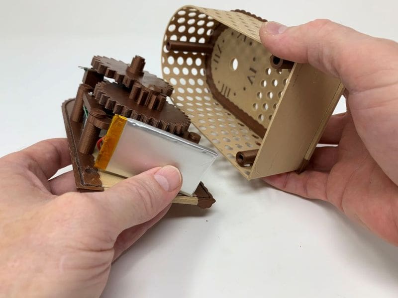
- Now attach the clock’s frame to its rear. This is done by pressing three magnets into the three small holes in your 3D printed rear. You will then thread four 3D printed standoffs into the clock’s rear assembly before positioning the frame assembly onto these standoffs. Use 3D printed bolts (6 mm x 8 mm) to secure the two pieces together.
- Assemble the clock’s front by threading three 3D printed standoffs into the 3D printed front and adding the cover, which is optional.
- Assemble and attach the clock’s door. Press the magnets into the holes of your 3D printed door. The rear assembly magnets must align with those on the door. Screw the 3D printed doorknob into the clock door and attach the USB cable to the Adafruit Feather Board. Let the cable come out from the rear.
In case you are using a battery, plug it into the Feather ESP32 battery connector. Then, while taking care not to break the reed switch, align the clock’s front assembly onto its rear assembly. Join the front assembly to the clock rear using 3D printed bolts (6 mm x 8 mm).
The hour gear will hold the hour hand while the minute gear will hold the minute hand.
Your clock is now ready: Power it up and watch it tell the time! (Unless you have something better to do…)
License: The text of " Auto-Correcting Analog Clock" by All3DP is licensed under a Creative Commons Attribution 4.0 International License.