3D Printed Circuit Board: How to Make Your Own

Check out this easy project tutorial to learn how to make your own solderless 3D printed circuit board using conductive epoxy.
A Dazzling Device
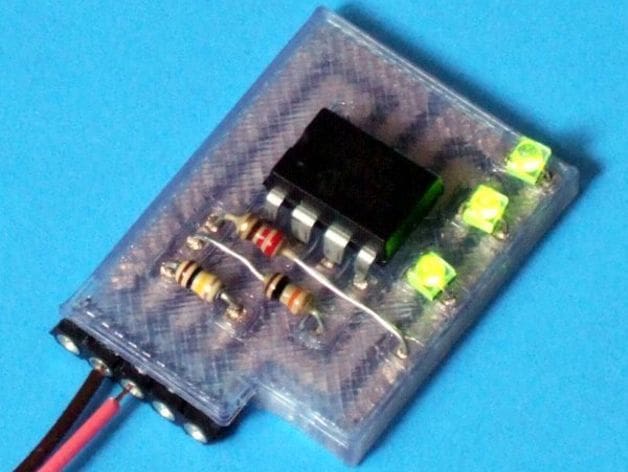
For this project, we make a 3D printed circuit board that flashes three LEDs in sequence. The original 3D printed circuit board, which we’ll be following, was made by Instructables user mikey77 — let’s call him Mikey. It used a conductive material for the traces; no copper cladding.
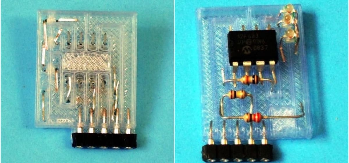
The solderless board resembles standard 1/16”-thick soldered perfboard and has holes for component leads. Below the holes are the printed channels, which are filled with epoxy after printing.
This is an experimental circuit board whose components can be easily connected without the need for soldering. And while it may not do much, it’s simply meant to be a small illustration of what’s possible.
Despite being easy to make, the circuit board requires some skill and attention to detail if you want to end up with a reliable device. Also note that Mikey’s original post is a little outdated, so we’ll need to bridge a couple gaps in order to replicate the results.
Design
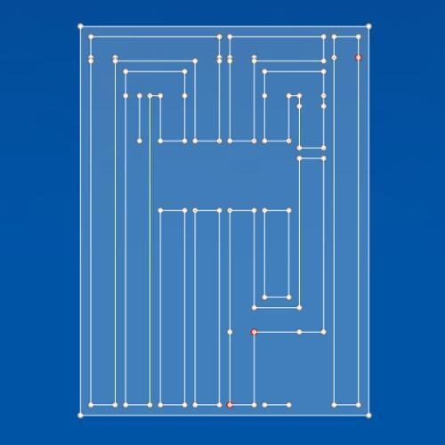
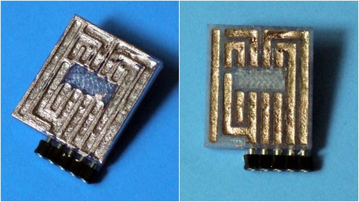
Mikey drew the circuit board’s design in 2D, keeping the walls .03” wide and the trace channels .07” wide. He then extruded the drawing to be .06” tall. That’s also the depth of the conductive trace channels, which are filled with conductive material.
Atop the board is a .03”-thick front panel with .07-square-inch holes for the components.
The DIYer mentions that you may end up with holes that are too small after printing. In that case, you can clean them out using a drill bit. (Alternatively, you can redesign the holes to be a little wider.)
Between the trace channels is the standard .01″ spacing. The conductive material can be anything from commercial conductive paint to conductive epoxy.
What You'll Need

The STL file can be found on Thingiverse.
Materials:
- PLA
- PICAXE-08M2 microcontroller (or any other controller, as long as you’re able to program it yourself!)
- Conductive epoxy
- 3 LEDs
- 3 resistors (one 10kΩ, one 100kΩ, and what appears to be one 22Ω)
Tools:
- Sandpaper
- Eyedropper
- Drill bit
- Toothpick
- FDM 3D printer
Naturally, if you don’t have access to a 3D printer, you can always outsource the printing to a 3D printing service. To help you find the best service provider for you, check out All3DP’s Price Comparison Service. We provide real-time prices from a variety of companies, like Shapeways, Sculpteo, and i.Materialise.
Order high-quality, custom 3D parts online at the best prices possible with Craftcloud by All3DP

Mikey programmed the Picaxe microcontroller using a simple script, which appears in his Instructables post. For more information on how to do this, check out Picaxe’s website.
Assembly
First, populate your board with the required components, then cut and bend the leads. Note that the electrical connections will be better if you have longer leads. As such, it’s a good idea to double-bend them. Once the components are in place, it’s time to glue them.
Ensure that the epoxy is filled to just below the height of the walls. Use a toothpick to make sure all the leads have enough contact with the substance. If you want a better electrical connection, you’ll have to take extra care in making sure the leads are well bent and well smeared with the conductive material.
Let your assembled parts dry overnight at room temperature.
As drying occurs, you’ll notice that the conductive material shrinks. This means you need to touch up the traces. Fill any gaps, holes, or bubbles with fresh epoxy. After it dries, use sandpaper to eliminate any conductive material that may short the traces.
Your circuit is now complete and ready for testing.
An important note: Your conductive material should never be allowed to freeze. It’s also advisable to seal your entire circuit – after it has been tested – using a sealer like silicone to prevent oxygen or moisture from entering. Embedding the circuit in epoxy or silicone will help in preventing the components from losing their connections or shifting as a result of pressure or vibration.
Mikey admits that, while this 3D printed circuit board may not replace traditional soldered circuits anytime soon, it is a step closer to the fully-automated 3D printed circuit. As mentioned earlier, the purpose of the circuit is simply to demonstrate what’s possible with 3D printing.
Feeling adventurous? Try programming your own program into the microcontroller!
CERTAIN CONTENT THAT APPEARS ON THIS SITE COMES FROM AMAZON. THIS CONTENT IS PROVIDED ‘AS IS’ AND IS SUBJECT TO CHANGE OR REMOVAL AT ANY TIME.