![Featured image of [Project] NeoPixel Bike Light](https://i.stageall3dp.com/workers/images/fit=scale-down,w=1200,h=675,quality=79,gravity=0.5x0.5,format=auto/wp-content/uploads/2018/11/28140847/adafruit-industries-youtube-181128.jpg)
[Project] NeoPixel Bike Light

This week, Adafruit shows us how to make a sci-fi-inspired bike headlight, inspired by jet engines and rocket boosters. Cycle through various colors and animations with the RGB LED button.
Introduction
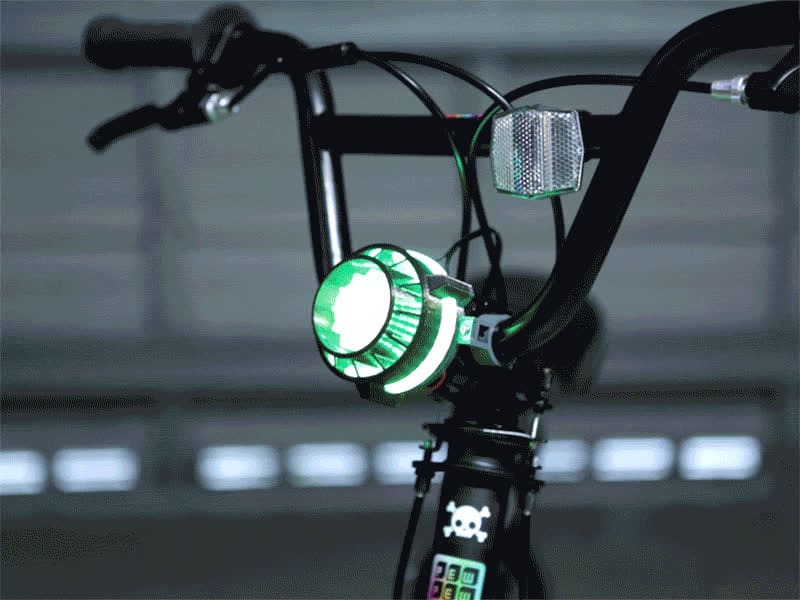
Using their NeoPixel and Feather products as the main components, Adafruit has built a sci-fi-inspired bicycle headlight that can navigate through a variety of colors and animations. All of the parts (for building this project) are available to download, so you can remix and remodify.
Let’s get to work!
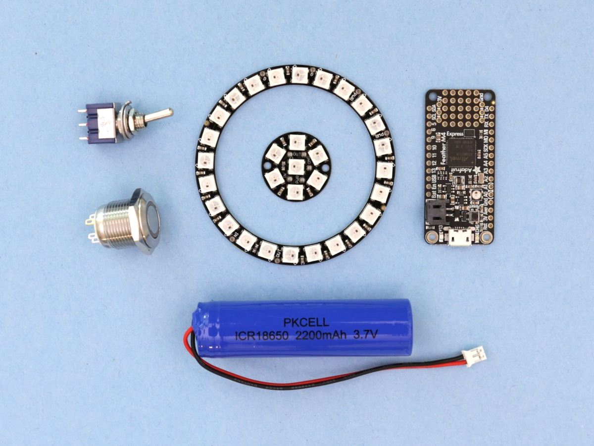
What You Need
Main Components:
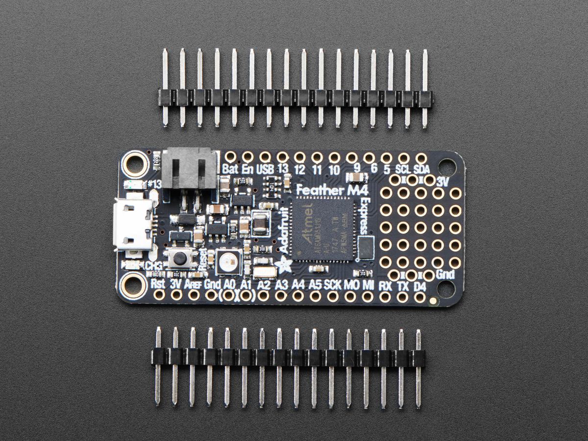
- Adafruit Feather
- Mini panel mount SPDT toggle switch
- 7x NeoPixel Jewel
- 24x NeoPixel Ring
- Lithium ion battery (3.7 V, 2200 mAh)
- Rugged metal pushbutton (16mm 6V RGB momentary)
- 28AWG silicone cover stranded-core ribbon cable
Hardware Supplies:
- JST-PH connector kit
- JST-PH 3-pin – female
- JST-PH 3-pin – male
- JST-PH 4-pin – female
- JST-PH 4-pin – male
- JST-PH 2-pin – male
- JST-PH 2-pin – female
- 4x M3 x 8 mm (pan head)
- 4x M2.5 x 5 mm (flat head)
- 4x M3 nylon locknuts
- 7x M3 x 6 mm (pan head)
- M2.5 & M3 screw taps
Adafruit picked the Feather platform because it comes fully featured and can be expanded using FeatherWing add-ons. This board has USB charging and comes with CircuitPython. Check out the newest version of CircuitPython and, if necessary, update your board before you begin your building process. Install the NeoPixel library for Circuit Python, then upload the code.
Tools:
- Soldering iron
- Solder wire
- Wire strippers
- Wire cutters
- Small vise
- Suspended magnifying glass
For printing, Adafruit recommends the Ultimaker 3 (for dual extrusion) and the Monoprice Inventor II (for single extrusion).
Printing
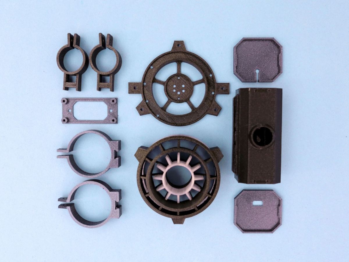
Here are the STL files. The pieces need tight tolerances, and this may mean having to adjust slicer settings.
- Clips: Before printing the clips for the bike frame, take into consideration that bikes come in different sizes. Therefore, you should first measure your bike’s frame to ascertain that the clips can fit. If they can, 3D print the mounting clips and try to attach them to your bicycle frame. You may have to use a filling tool in case the tolerances are tight.
- Headlight: The headlight is designed for dual extrusion using dark (black) and translucent PLA. Alternatively, if you don’t have a dual extrusion printer, you can print the entire headlight using translucent PLA then mask certain parts with acrylic paint. The translucent filament will illuminate light from the NeoPixels and will aid in diffusing light.
- Box enclosure: One section of the box enclosure has a “grill”. Printed using a colored filament, this has no real function and is purely to make it more appealing.
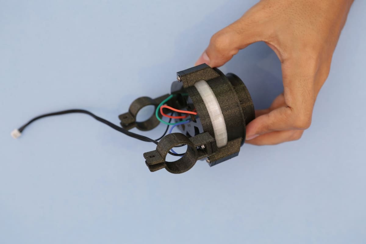
- Mounting plate: The mounting plate houses the Adafruit 24 RGB LED NeoPixel Ring and the 7 RGB NeoPixel Jewel.
Adafruit used Ultimaker’s CURA, recommending 20% infill, 60-mm/s printing speed, 0.2-mm layer height (with a 0.4-mm nozzle), and 0.38-mm line width (inner and outer widths).
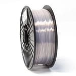
Adafruit went for Rapunzel Silver PLA and Vertigo Galaxy PLA. These options were picked from Fillamentum’s ExtraFill filaments.
Wiring and Soldering
The basic steps for wiring and soldering are the following:
- The RGB pushbutton requires six wire connections to connect it to the Feather. Ensure the polarities match before soldering. Hold the button with the vise while soldering.
- The toggle switch requires two wire connections. This switch comes with three pins, however, you will only need two pins: the middle one, and either of the remaining two. Solder the wires to the two switch pins you pick.
- At this point, your switch and button are wired by JST-PH wires. Now, solder the matching wires to the Feather. You will need to take your time to figure out which wire goes where, ensuring that the polarities are matching. The cables from the RGB LED button and the switch should go to their corresponding places in the Feather.
- The Ring and the Jewel will require six connections. The Ring’s data-out connects to the Jewel’s data-in, and both are connected using three different wires. A JST-PH wire will then link the Feather to the Ring.
- Line up the holes of your 24x NeoPixel Ring with those of your printed mounting plate, and let the wires go through the openings of your mounting plate. The cables will be fused to the printed circuit board (PCB). The Jewel will also fit to the center of this mounting plate. Check that the connections coming from the 7x Jewel are going into the right pins of the 24x Ring, then use some tweezers to assist in soldering. Note that the wires need to be kept away from the light source.
- Finally, you must fuse the 3-pin JST cable to the Feather. The polarities must match!
At this stage, your headlight is ready for assembly, but not before you test NeoPixels. First, ensure that they are wired the right way. Then use a NeoPixel example code to test the NeoPixels. The testing process may involve updating and uploading the code. Plug in the battery, and you are ready to go.
Joining Parts
Here’s how to put it all together:
- Align your 3D printed headlight diffuser with the holes of the printed mounting plate and press them against each other. Use screws to ‘lock’ the mount to the headlight and install mounting clips on your now assembled headlight. The clips will be held in place using screws. The Feather also needs to be held in place on its mounting plate and secured with screws.
- The LED pushbutton and the toggle switch are installed on the printed box. Both of them need to be flush with the box’s surface on different sides. The mounting plate holding the Feather will then be secured to the enclosure. The battery will go on a circle-like clip inside the cabinet. With both the Feather and battery inside the enclosure box, you need to attain the right orientation to enable you to screw everything into place.
- Get hold of all the JST cables from the LED pushbutton, switch, and Feather. Make sure they are out of the box, so they can be connected with their matching cables. Follow the connections to confirm they are corresponding, and do not mix anything up. The only wire that will be left protruding is the JST-PH (3-pin) connector, which will be fused to the NeoPixels.
- Connect clips to the 3D printed enclosure. Use a filing tool in case the tolerances are extra tight. At this stage, it is advisable to perform another test. Join the JST-PH (3-pin) cables and the switch to test your new circuit. Your headlight should be powered on. Think of where you are going to clip this box. Adafruit clamped theirs to the bicycle frame for ease of access. They then attached the headlight onto the handlebars.
- With the clips clamping onto the frame, secure them with screws and a locknut. The headlight clips will also need to be tightened onto the tubing with screws. These clips should NEVER obstruct the bike when controlling. The RGB LED button will be used to cycle through different colors and animations on the NeoPixels.
Whenever you connect the Adafruit Feather to a computer, you get a chance to access the code and the libraries (as it will show up as a flash drive). The code – which is written in Adafruit’s Circuit Python – lives on the drive to allow for quick code changes without the need for an IDE.
If you think these steps to be too complicated, Adafruit has excellent resources to take you through soldering as well as handling the Feather M4 Express, Circuit Python, and NeoPixels:
- Adafruit Feather M4 Express Intro
- Welcome to Circuit Python
- NeoPixel Uber Guide
- Adafruit’s Guide to Excellent Soldering
Enjoy your new multicolor bike light!
License: The text of " NeoPixel Bike Light" by All3DP is licensed under a Creative Commons Attribution 4.0 International License.
CERTAIN CONTENT THAT APPEARS ON THIS SITE COMES FROM AMAZON. THIS CONTENT IS PROVIDED ‘AS IS’ AND IS SUBJECT TO CHANGE OR REMOVAL AT ANY TIME.