![Featured image of [Project] Wi-Fi Round LED Clock](https://i.stageall3dp.com/workers/images/fit=scale-down,w=1200,h=675,quality=79,gravity=0.5x0.5,format=auto/wp-content/uploads/2019/04/17234511/wi-fi-round-led-clock-christian-schmied-all3dp-190417_download.jpg)
[Project] Wi-Fi Round LED Clock

This stylish clock not only shows you the current time but is also an eye-catcher in your room. With a 3D printer, a couple of electronics and a free weekend, you too can have the time of your light.
Wi-Fi Round LED Clock
The Wi-Fi Round LED Clock by leonvandenbeukel is a combination of stylish lighting and an analog clock in today’s digital world. With the “hour hand” glowing in red, the “minute hand” in green, and the “second hand” in blue, it’ll always be disco time.
The 3D printed clock consists of an LED strip with 60 LEDs and is controlled by a microcontroller. It ‘s connected via Wi-Fi and periodically retrieves the current time from a time server. Automatic summer and winter time conversion is, of course, also included.
The 3D printable parts print within a few hours, and the electronic components are inexpensive and easy to come by. So basically, there’s no reason not to 3D print this clock. Even if you’re a beginner in DIY 3D printing projects, the electronics part is very small, with clear instructions, so there’s no need to worry.
Ready to impress your family and friends with what you can do with a 3D printer? Let’s get started!
Step #1: Gathering the Parts
The Wi-Fi Round LED clock consists of six parts for the ring (frame) and 60 tiny little squares for the minute markers that snap into the frame. Furthermore, you’ll need four brackets and a suitable case for the ESP8266. All STL files can be downloaded for free on Thingiverse.
Prints
The ring should be printed in a solid color, such as black, and the little squares need a translucent material or simply white PLA so the light can shine through. The parts for each 5-minute marker are a little bit bigger than the others, but only slightly. So if you want there to be more visibly different, you might consider printing them in a different color. Either way, you’ll need to 3D print 48 pieces of the smaller squares and 12 pieces of the bigger ones.
Parts
The following non-printed parts are needed for the assembly:
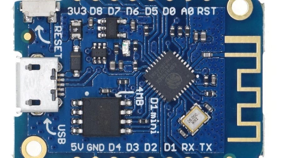
- WeMOS D1 Mini ESP module
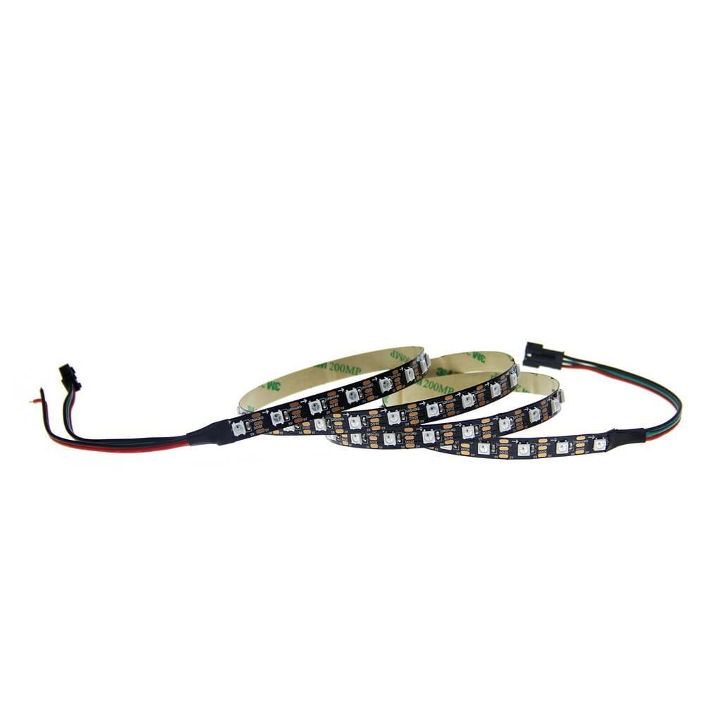
- LED strip WS2812B 60 RGB LED’s 1 meter
- 5-Volt power adapter
- Micro USB cable
- 3-pin wire
The original BOM on the Github page of leonvandenbeukel also lists other parts like jumper wires or a breadboard, but it’s better and more reliable to solder the cables directly. Also, the USB breakout board is not required, because the Wemos D1 has already a micro USB socket!
The one technical aspect you’ll need to for programming the ESP8266. For this, you’ll need Arduino IDE with the necessary USB drivers and libraries, especially the “FastLED” library, installed. But once you have the program, the code is already written out so you need only copy and paste.
Download the files: Wi-Fi Round LED 3D Printed Clock
Step #2: Printing the Frame
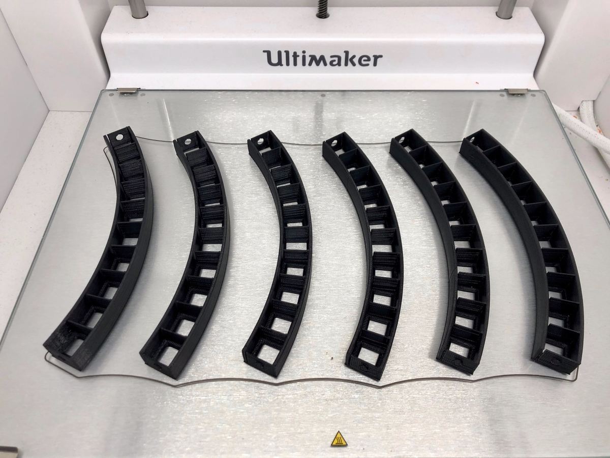
3D printing the required parts is hassle-free. You don’t need any special settings. As mentioned, you’ll want to 3D print the segments for the frame in a solid color, such as black. Not much material is needed, but due to the shape of the segments, you should allow some time for printing all the pieces. So it’s good to start with these segments earlier in the weekend.
The little square covers for the minute markers must be somewhat translucent. A light color such as white is optimal here. We recommend setting the layer height to 0.1 mm. This ensures you get two layers for the thin part of the cover.
Before printing all 60 pieces in one match, you may want to do a test batch with just one of each size to make sure they snap easily into the ring. You don’t want to have to re-3D print all of them if you find out a setting was off! In our case, we had to scale the parts to 98.9 % to make them fit perfectly.
Step #3: Assembling the Parts
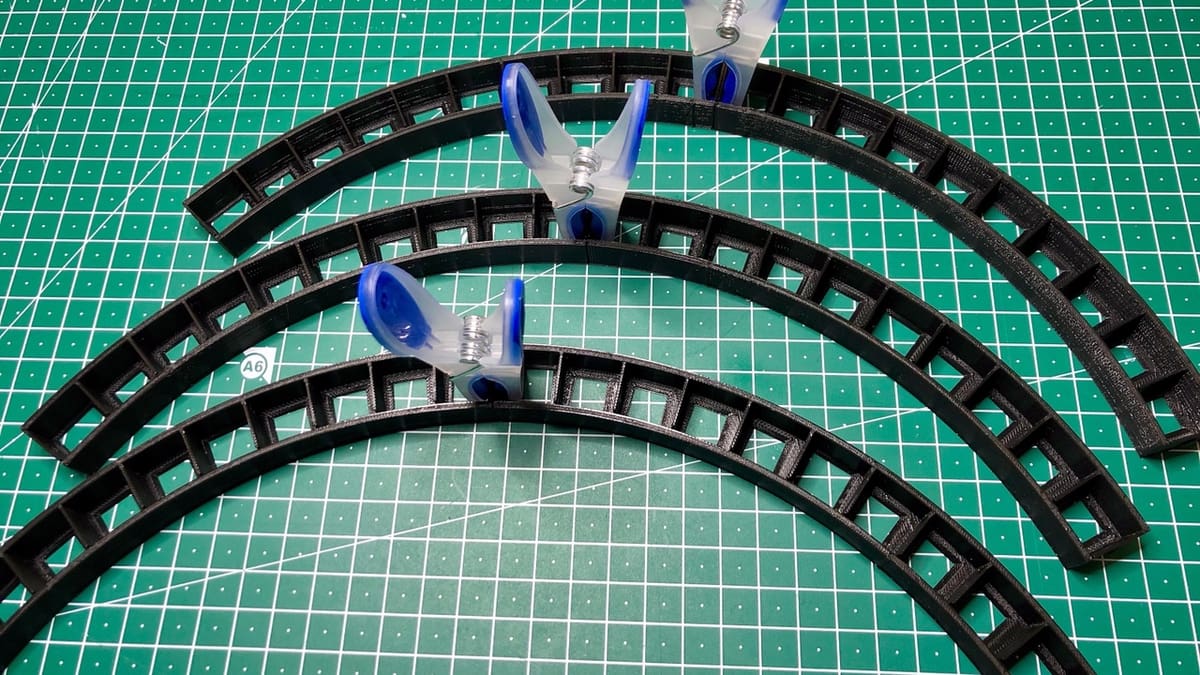
After printing, the individual segments of the ring are glued together. Be careful here though, the segments are a bit fragile and aren’t so easy to handle. We had some difficulties keeping the segments in place while the glue was drying. Therefore, we recommend taking some clothespins to hold the parts together and not gluing everything together at once. What we found to work best was to glue just two parts together at a time, and then glue the whole ring together once those pieces had dried.
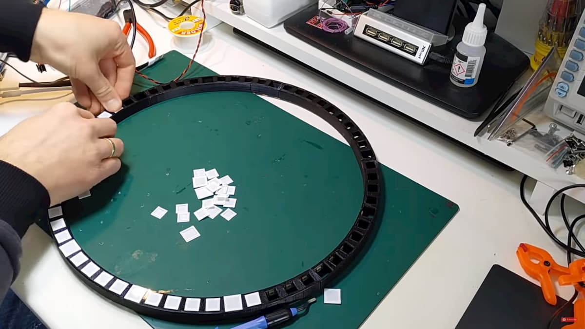
Mounting the minute covers is easy if you have carefully checked the clearances before with a test print. Then they should fit perfectly and snap into place, needing no glue.
After the glue is fully dry (be patient), the LED strip is simply inserted and the connecting cables are soldered according to the instructions. You just need a 3-wire cable, power, grounder (GND), and data, that’s it!
Finally, the four wall brackets are glued on to be able to mount the clock with a little distance from the wall.
Step #4: Avoiding Electrocution (Just Kidding, but Not Really...)
The last step is the “complicated” part: connecting the electronics. But not worry, it’s not actually complicated. In fact, it’s quite simple.
The LED strip is connected to +5V and ground (GND) on the ESP8266. Additionally, you have to connect PIN D6 to the Data PIN of the LED strip. If you’re not so experienced in soldering, you can use the existing cables on the LED strip and simply extend them to the required length.
Then, download the INO file from Github, load it into Arduino IDE, and input the Wi-Fi SSID, Wi-Fi password, and timezone to match your settings. Once everything is set, use the Upload function in Arduino IDE to upload the program to the microcontroller. If you have trouble, check out these step by step instructions on how to prepare your Arduino IDE.
After transferring the software to the ESP8266, the program will start and the microcontroller will connect to Wi-Fi and retrieve the current time from the Internet.
The red LED is to show the hour, the green for minutes, and the blue one for seconds. You can change the colors as you like, you just have to change the color names in the source code and upload it again.
There’s one little thing we don’t like that much. The hour display always remains the same until the end of the hour and doesn’t move as with a normal analog clock. Fortunately, this can be fixed with a small change in the software. The software change for this can be found in the comments on Thingiverse.
Last but not least, check out this video of this 3D printed clock project from start to finish:
Have fun with your new gadget!
Feature image source: leonvandenbeukel / Thingiverse