Troubleshoot Your 3D Printer with an XYZ Calibration Cube

Wonky tolerances or other issues? 3D print a calibration cube and follow our guide on XYZ calibration cube troubleshooting.
3D printer calibration, the act of changing a 3D printer’s firmware to increase stepper motor precision, is a tricky but very necessary task for 3D printer owners. After all, a 3D printer’s printhead can only be as precise as its carriage, which is controlled by these stepper motors.
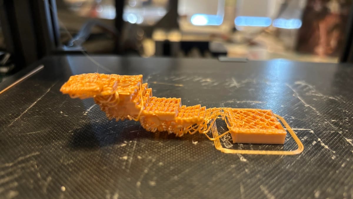
An uncalibrated 3D printer might be able to print miniature statues or desk toys effectively, but unless it’s properly calibrated, it may be incapable of printing mechanical parts or the articulated models that have become so beloved within the 3D printing community.
There are many ways to calibrate a 3D printer, but a well-established method of troubleshooting a 3D printer’s precision is by using a calibration cube. Spending 20 to 30 minutes printing a calibration cube and checking its tolerance is a good way to avoid wasted time and filament – an ounce of prevention can (literally) be worth a kilogram of filament!
When to Use One
There are a few occasions in which it would be a good idea to print a calibration cube:
- You have a new printer that hasn’t been calibrated yet, or you plan to use a printer that has been sitting idle for a while.
- You’ve made modifications to the printer, such as changing belts, motors, or modifying the frame in a permanent manner.
- You notice that your prints aren’t the same size as the digital models indicate in one or more directions.
- You’re printing a model that requires tight tolerances – 0.15 mm or smaller.
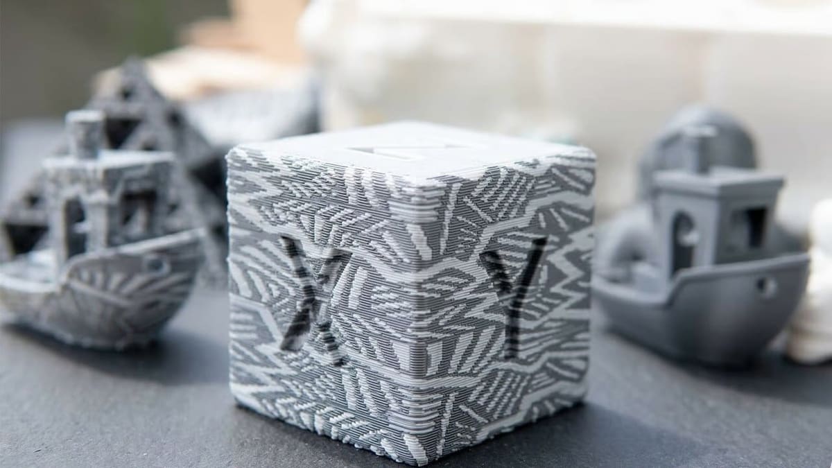
Thanks to specific length, width, and height measurements, calibration cubes show the precision of the printer’s movements primarily along the X- and Y-axes. They’re not 100% accurate for calibrating the Z-axis because the print bed’s flatness also impacts this axis.
In addition to dimensional accuracy, calibration cubes will show whether your 3D printer is experiencing common 3D printing problems such as ghosting, elephant’s foot, bed leveling, or extrusion issues. Below, we’ll show you how to calibrate the stepper motors driving your printer’s axes using a calibration cube, but to resolve these other issues, you’ll want to consider calibrating the extrusion multiplier and E-steps as well.
Getting Started
Troubleshooting stepper motor precision using a calibration cube is a fairly straightforward process but requires several tools (both physical and software-based) to be done correctly and successfully.
What You’ll Need
- A Cartesian or CoreXY 3D printer that needs to be calibrated. Unfortunately, it’s too mathematically intensive for this guide to tune a delta 3D printer using a calibration cube because more than one stepper motor is responsible for each axis.
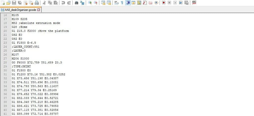
- A 3D printer slicing program that can directly send G-code commands to a connected 3D printer – see our software recommendations below.
- A connection between your 3D printer to computer. This could be a USB cable, over Wi-Fi, or any method that will allow your 3D printer to connect to your computer.
- Reliable 3D printer filament, preferably with a tight tolerance. This will help improve accuracy because 3D printer filament with a small tolerance will lead to 3D prints with a small tolerance. This allows you to be more accurate when tuning your 3D printer using a calibration cube.
- Reliable digital calipers.
- A digital file of a calibration cube.
- A calculator, as this guide requires some multiplication and division.
Software Considerations
Repetier and Pronterface are good options for sending G-code commands to your printer. They’re preferable to other more typical G-code editors because you can send G-code commands in real time instead of having to create and run several G-code files using a USB stick or SD card.
Keep in mind that if you use another 3D printing slicer for this task, it should have the ability to directly send G-code to your 3D printer, which is not currently available in slicers such as Cura without the use of extensions.
Alternatively, if your 3D printer runs on Marlin firmware and you’re experienced with programming, you could also directly edit the firmware using an IDE without using G-code.
Printing
It’s crucial to keep a few things in mind, here. First, it’s very important that the 3D printer’s build plate is leveled correctly. This ensures that the calibration cube can better demonstrate the 3D printer’s Z-axis precision.
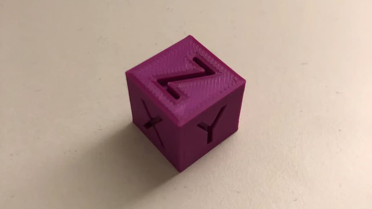
Second, if you’ve selected a calibration cube that has labels for the X-, Y-, and Z-axes on the cube’s walls, make sure that, in the slicing program, the walls are parallel to the axis that it’s supposed to measure.
Some calibration cubes will automatically be imported facing the correct direction. You can always check that the cube is oriented correctly in your slicer because most slicers will have a red arrow that points in the direction of the X-axis, a green arrow that points in the direction of the Y-axis, and a blue arrow pointing in the direction of the Z-axis.
Make sure to also use the slicer settings that you’re going to use once the 3D printer is calibrated. Once everything’s all set, print the calibration cube as you would any other 3D print.
After the cube has been printed, be sure to verify which side corresponds to which axis. If you don’t know which axis faces which direction of your 3D printer and you’re using either Repetier or Pronterface, you can test this by manually moving the X-axis and observing in what direction the extruder moves. This direction is your 3D printer’s X-axis.
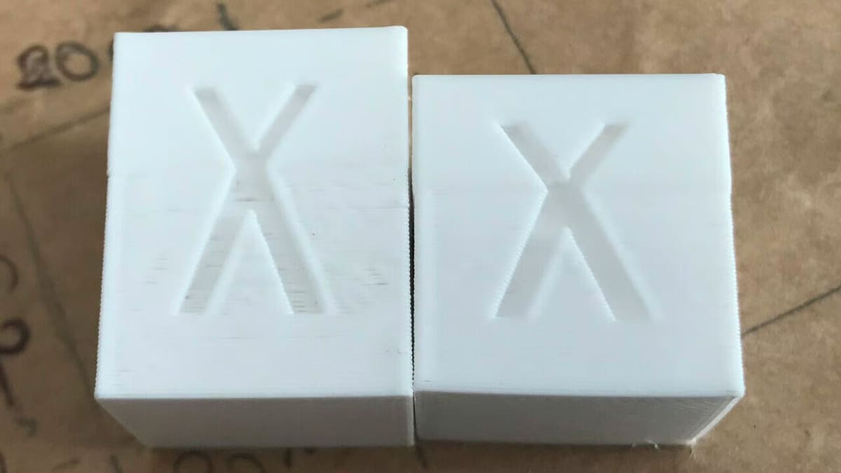
Measuring
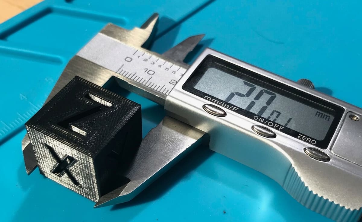
Once the calibration cube is printed, carefully remove it from the build plate. Then, use digital calipers to measure all three sets of sides of the calibration cube – a ruler may be too imprecise to be effective with such precise calibration. Finally, record these measurements as well as the corresponding axis for each measurement.
For example, if the caliper shows that the side labeled ‘X’ is 20.25 millimeters, record (in writing or on a digital note-taking app) that the cube’s X-axis measures 20.25 millimeters. Do the same for the other two axes.
Interpreting the Calibration Cube’s Measurements
In the slicer, the calibration cube that you select will be a set length, width, and height (corresponding to the X-, Y-, and Z-axes). These values are normally included in descriptions of individual calibration cubes that you might select, but this might not always be the case. If not, 3D printing slicers such as Repetier allow users to see and modify these values by clicking either the ‘S’ key on the computer keyboard or the “Scale” button on the object editing menu when the calibration cube is selected.
Once you have these three theoretical values, compare them to your measurements of the calibration cube that you printed. If they match almost exactly (typically within 0.025 mm), your 3D printer is perfectly calibrated! The only thing that you can do to increase your 3D printer’s precision from here is switch to a filament with a tighter tolerance.
Sometimes, one or more of the measurements do not match. For example, you may get an actual measurement of 19.9 mm for a side that’s supposed to be 20 mm. It could be more extreme: You get an actual measurement of 24.4 mm. If that’s the situation you’re in, the calibration cube has demonstrated that the 3D printer needs to be calibrated using a bit of math and G-code editing.
Calibrating Your 3D Printer
To calibrate your 3D printer, you’ll need to use a series of G-code commands to change the amount of steps that your 3D printer’s stepper motors will rotate for each millimeter travelled. It’s a straightforward process but can be a bit tedious, so make sure to double-check each step to avoid getting numbers and commands mixed up.
- Connect the computer to the 3D printer using a printer cable or another method.
- Open Repetier or another 3D printing slicer that allows you to send G-code directly to the 3D printer.
- Connect the 3D printer to the 3D printing slicer. If you’re using Repetier, click on the large “Connect” button on the top left of the program. Then, navigate to the manual G-code input – on Repetier, this is under the “Manual Control” tab.
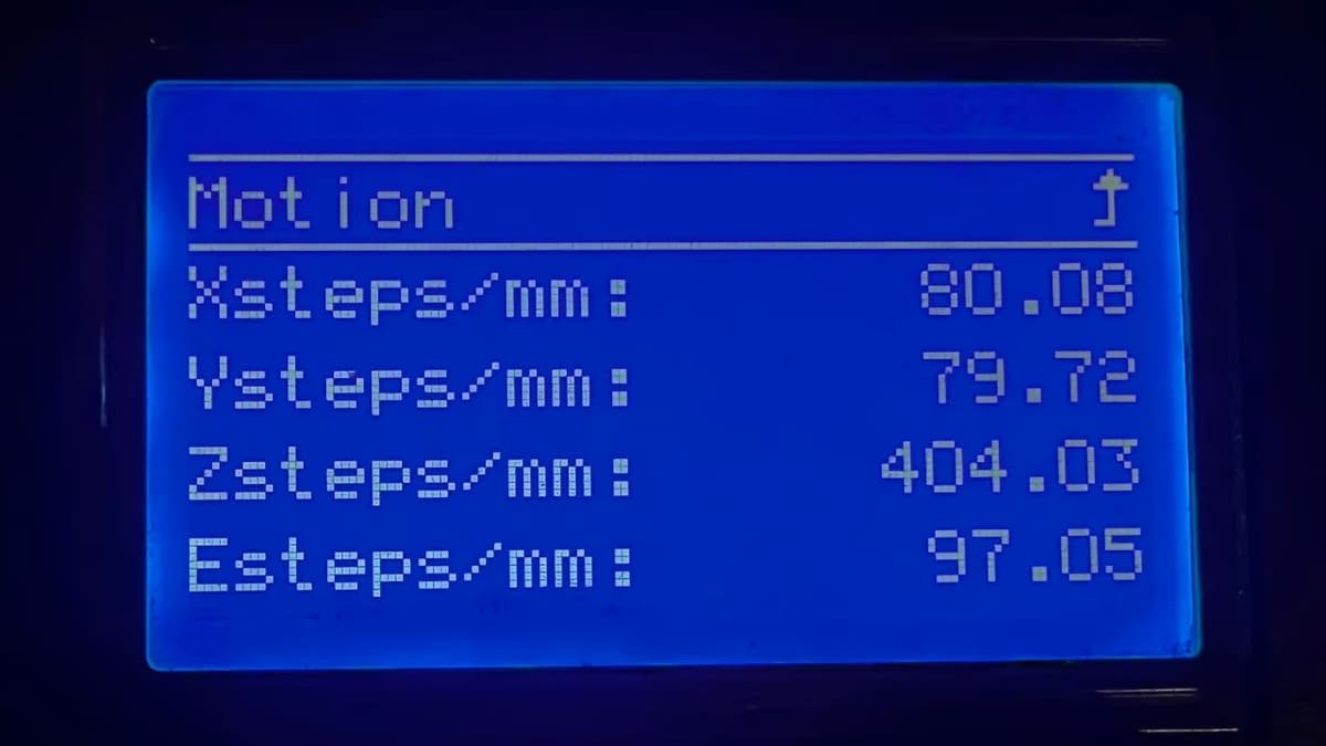
- Type in the command
M92, then hit “Send”. It should return the number of steps per millimeter for each axis. This is the number of small incremental movements that a stepper motor will make to move the extruder a distance of one millimeter. Remember or record the steps per millimeter for each axis. - For each axis, divide the theoretical length of the calibration cube for that axis (the digital length of the calibration cube) by the actual length of the calibration cube on the same axis (the one found using calipers).
- For example, if a 20-mm calibration cube had an actual X-axis measurement of 21 mm, this ratio would be 20/21, or 0.9523. Record this ratio for each axis.
- For each axis, multiply the ratio of theoretical length to actual length by the steps per millimeter that was returned by the M92 G-code command.
- So, if the M92 command returned the value “x78.5” (meaning that the steps per mm along the X-axis was 78.5) and the ratio of theoretical/actual was 0.9523, the new steps per millimeter would be 0.9523 * 78.5.
- A more condensed version of this formula is that, for each axis, the new steps/mm = old steps/mm * (theoretical length/actual length).
- Calculate the new steps/mm value for all three axes.
- Check to make sure that your numbers are correct. An intuitive way to check is that if the actual length of the cube on a particular axis was too small, the new steps/mm value should be larger than the previous one, and vice versa.
- Type
M92into the command line again. Before hitting send, add the letters of each axis followed by the new steps/mm value that you calculated.- For example, if all new step values were 100, the command would look like
M92 x100 y100 z100.
- For example, if all new step values were 100, the command would look like
- Click “Send” or hit the enter key. If you realize you made a calculation error, that’s okay! The M92 command can be entered over and over again, although each use of the command will permanently save the new values that you entered as the new steps/mm for the 3D printer. Just make sure that the last time you enter the command, the numbers are correct because these numbers will not reset once the 3D printer is powered off; they’re written into the printer’s memory until another M92 command is sent.
Once these steps are completed, the 3D printer should be calibrated, and it should print accurately and precisely in all three dimensions.
Further Troubleshooting
While calibration cubes are most often used to calibrate the dimensional accuracy of your printer, they can reveal other issues that can be fixed using various techniques.
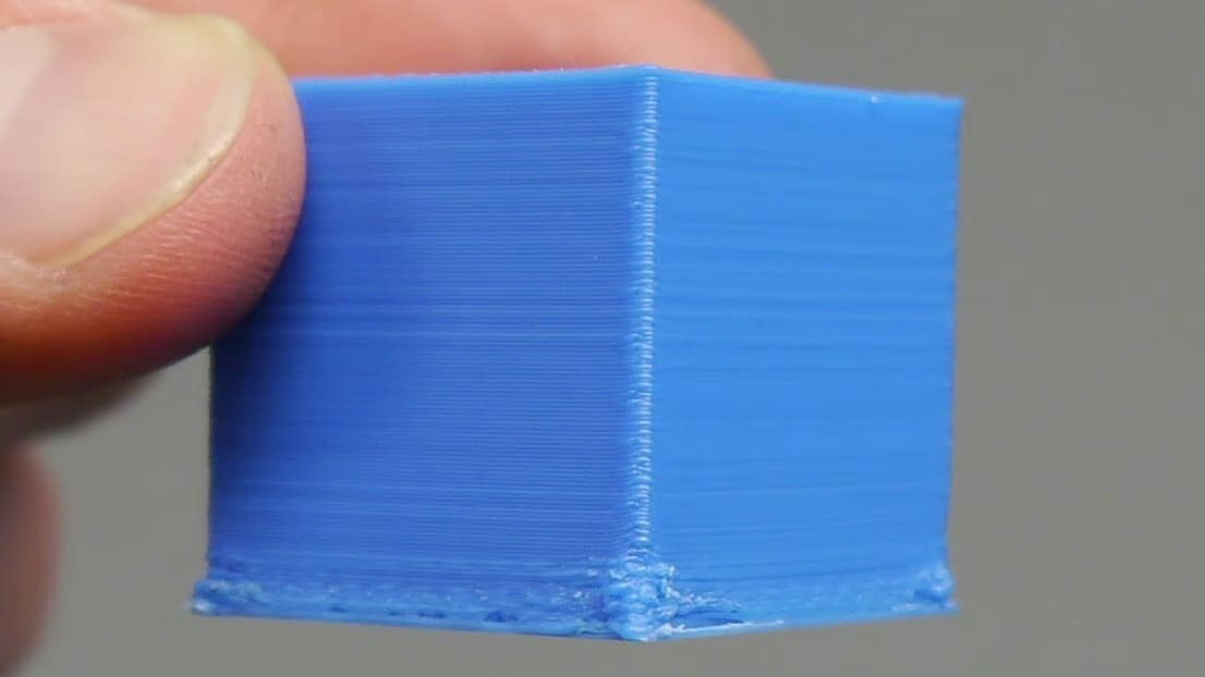
The calibration cube might exhibit elephant’s foot, where the bottom edges of the object are warped. If that is the case, the elephant’s foot can be fixed using a few different tested strategies for getting rid of elephant’s foot. The cube might also exhibit ghosting, which is most evident in surfaces that are wavy when they should be straight. This issue can also be fixed in a few easy steps, and your 3D printer’s overall print quality will increase substantially.
Hopefully, this article has demonstrated the usefulness of calibration cubes and likewise proved that they can be an integral part of a maker’s calibration process. The calibration cube itself, though, is just a part of the calibration process. If calibrating your 3D printer piqued your curiosity about G-code commands, check out our article on G-code commands to find out what other things you can accomplish with this 3D printer control language.

License: The text of "Troubleshoot Your 3D Printer with an XYZ Calibration Cube" by All3DP is licensed under a Creative Commons Attribution 4.0 International License.