9 Important 3D Printing Concepts Everyone Should Know

When learning about additive manufacturing, 3D printing concepts can be easily explained though 3D printed models. Try it for yourself.
One of the best ways of learning is by doing, and this is certainly true of 3D printing. Librarian Brian Wilson has developed these fantastic 3D printable models that clearly explain the basic concepts of additive manufacturing. The forehead-slapping simplicity is that they’re labeled with the principle that they’re illustrating.
These models are a great educational tool for the classroom, workshop or library, and also a great project for individuals starting out on the bumpy road of additive manufacturing.
Scroll through the images below to see for yourself, together with links to download each file. And special thanks to Brian for granting us permission to share his work.
3D Printing Concept #1: Tolerance
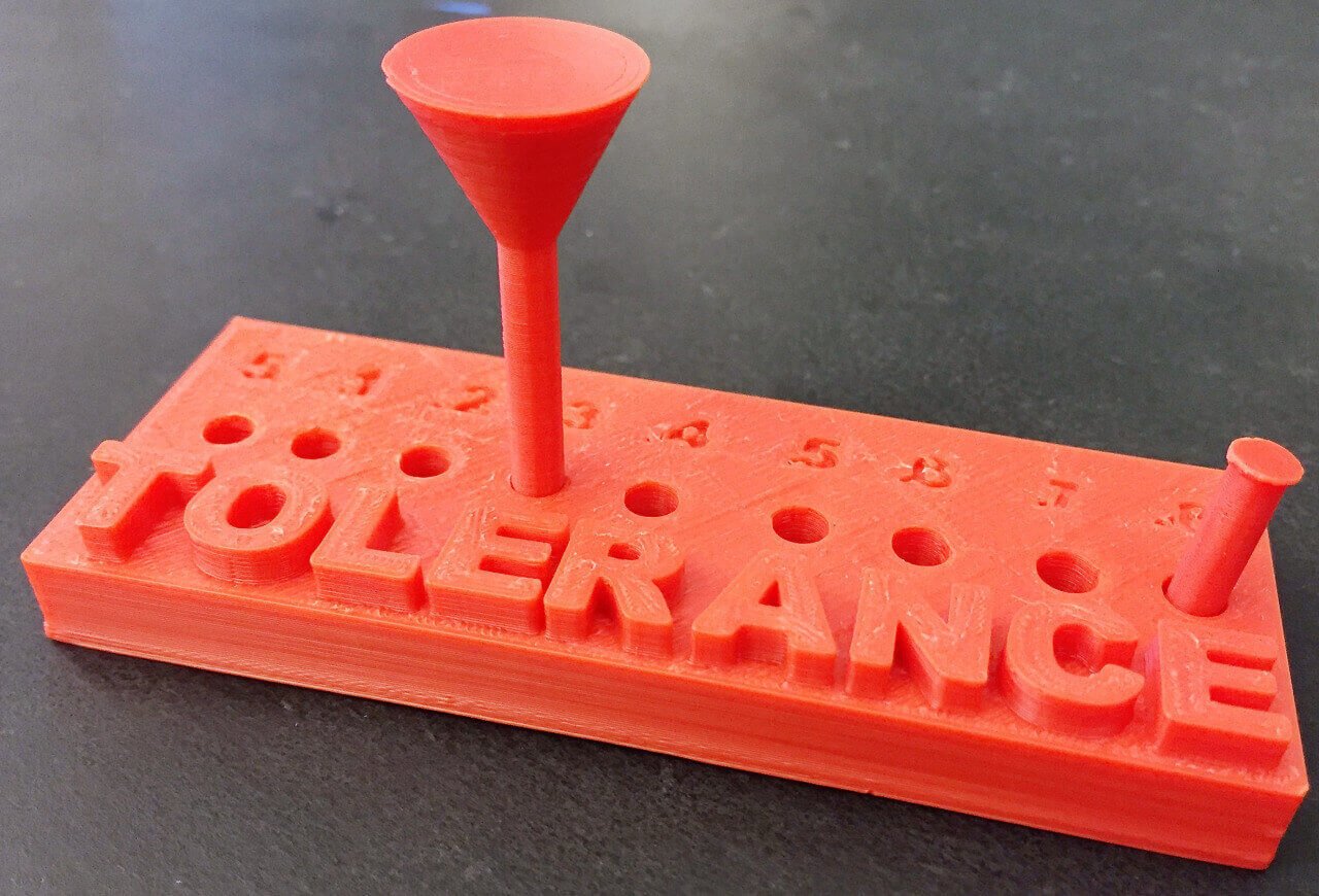
Tolerance shows the ability for parts to fit together, and is important when creating something like joints. Ensure there is enough space for tolerancing when creating moving parts, for example in 3D modeling software like SOLIDWORKS.
A great example of tolerance in practice is 3d printed ball joints, where there are no support structures in place between the socket and the ball. The ball joint comes fresh off the print bed, already articulated and fully rotating.
Download the STL files for your own use: tolerance
3D Printing Concept #2: Maximum Size
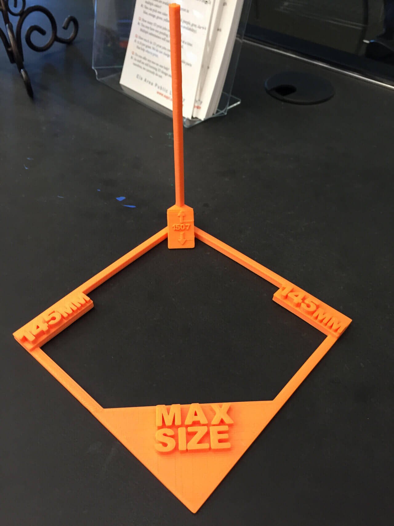
This model is a literal demonstration of the maximum size objects possible on a 3D printer, in this case a LulzBot Mini. It may seem obvious, but you should always keep the printable dimensions in mind when 3d modeling a printable object.
If your model falls outside the printable area of the 3D printer, consider breaking it down into smaller pieces that can be printed separately, or scale the size of the model to fit.
Download the STL files for your own use: max size
3D Printing Concept #3: Colors
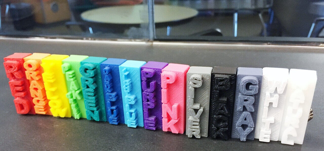
Color is critical in the look and feel of a 3D printed object; it has a significant impact on bringing out finer details, and complements the final design.
When evaluating the range of colors for a 3D print job, or demonstrating them to others, you could browse through a color swatch book. Or you could lug several spools of filament around. Or you could save yourself the trouble just by printing basic blocks of color with the shade labeled on it. Simple, but effective.
When printing them off, of course, remember to align the correct color filament to the label. Otherwise… CHAOS.
Download the STL files for your own use: colors
3D Printing Concept #4: Infill
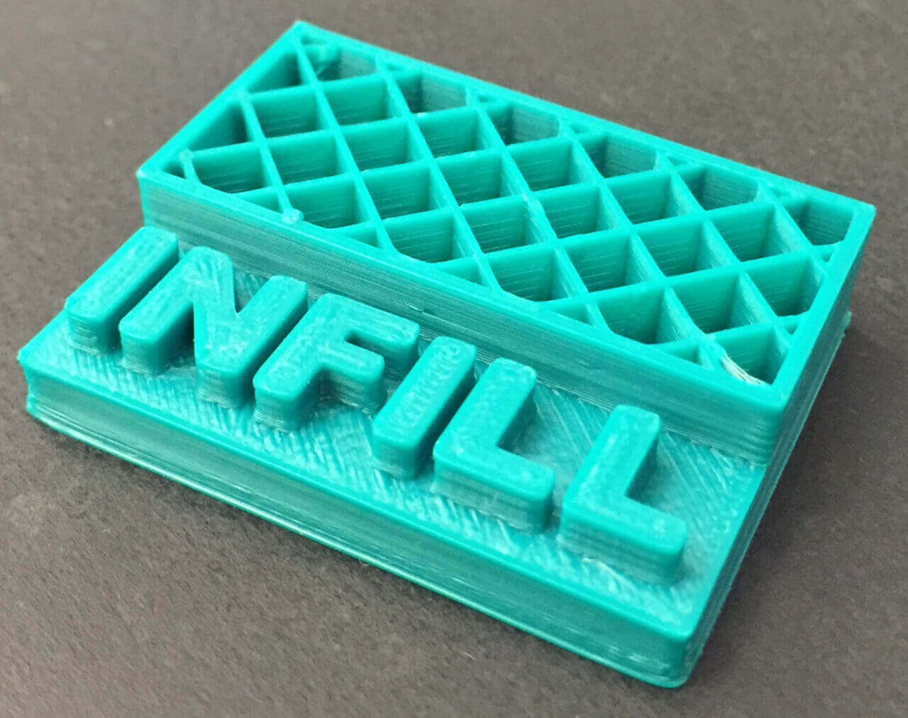
The principle of infill is that, for those interior parts of a model that will never be seen once the print job is completed, the infill doesn’t necessarily need to be 100% solid. Instead, it can be a basic honeycomb or diamond grid that provides structural integrity.
This model shows how one software slicer composes the interior structure by default, though it can be made more or less dense as per your requirements. The print was cancelled midway through to demonstrate.
The benefit of this principle is two-fold. First, it saves time when printing an object. Secondly, it reduces the amount of filament being used.
Download the STL files for your own use: infill
3D Printing Concept #5: Over Hang
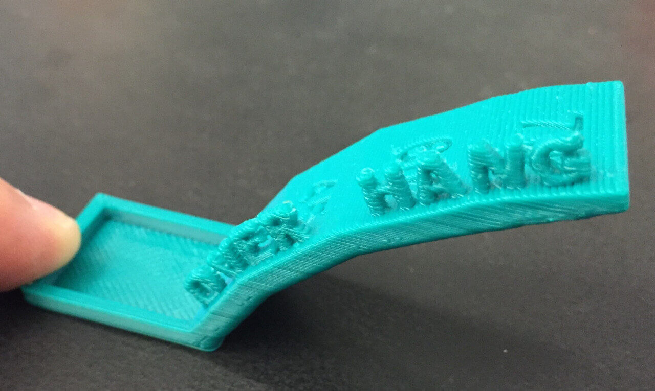
The Over Hang model shows the ability to print self-supported overhangs. As a general rule, you shouldn’t allow your model to have too many over hangs without anything under them. Anything at less than a 45 degree angle will require supports. Anything more than 45 degrees doesn’t need support.
Download the STL files for your own use: Over Hang
3D Printing Concept #6: Bridging
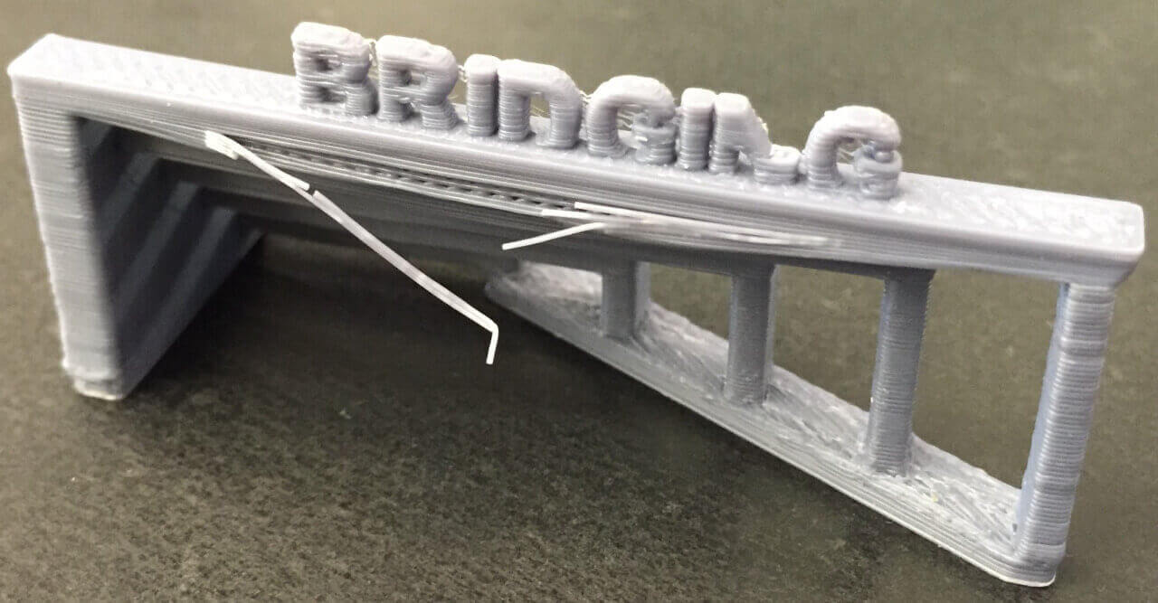
Bridging is self-explanatory. This model shows slight bowing when printing “bridges” across empty space between two solid shapes. The larger the space the bridge has to traverse, the more likely it will dip downwards as the fused filament cools.
One way to avoid the pitfalls of bridging is to consider the orientation of the model when it’s being printed. For example, let’s consider a small rectangular table for a doll’s house. Printing it upright — as you would normally visualize it — will cause bridging problems when the printer begins fabricating the surface of the table. But printing it upside down with legs in the air shouldn’t cause any problems.
Download the STL files for your own use: bridging
3D Printing Concept #7: Supports
Related to the previous concept, another remedy for bridging is to include removable supports (or rafts) in your print job. These will not not as detailed as the main body of the object, and are easily snapped off after the print has finished.
Download the STL files for your own use: supports
3D Printing Concept #8: XYZ
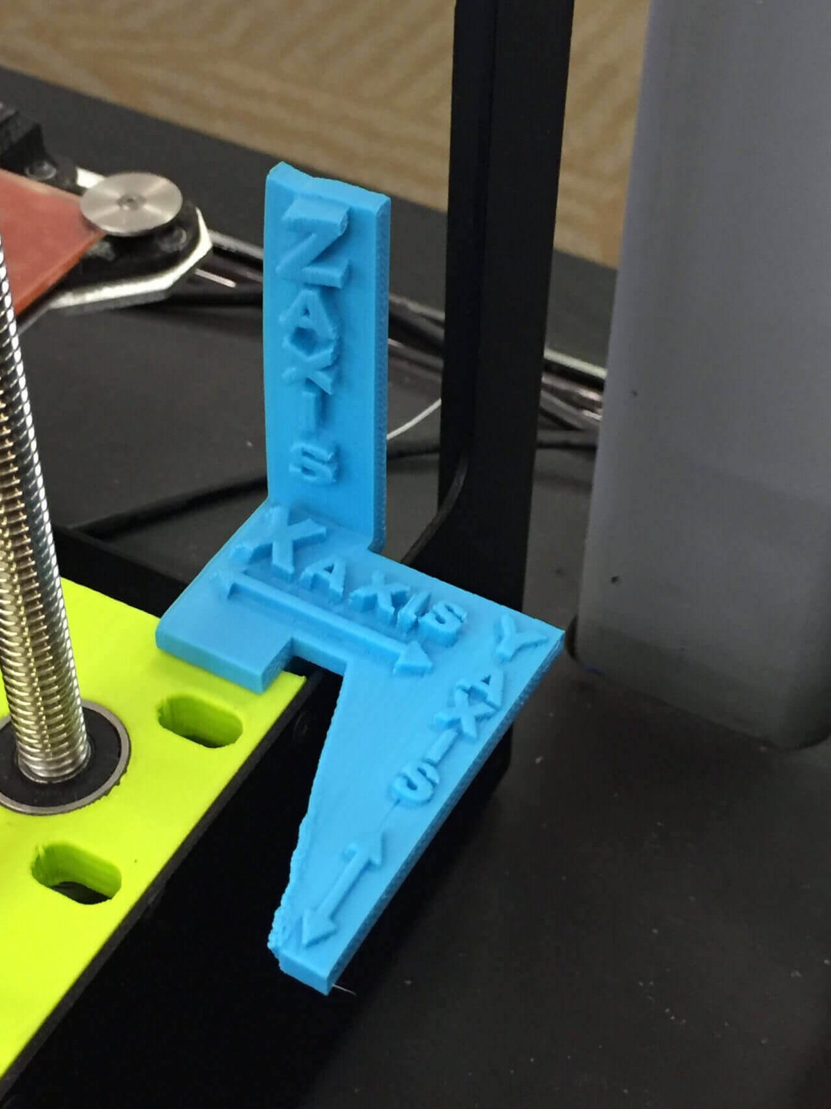
Here we have a visual demonstration of the separate axes — X, Y and Z — which are fundamental to 3D modeling. Coordinating the three together (via the instructions contained in an STL file) is how a 3D printer plots a point in space when fabricating a physical object.
This model can be attached to the 3D printer for handy reference, or perhaps propped up alongside your computer monitor when working with a CAD program.
Download the STL files for your own use: XYZ
3D Printing Concept #9: Polygons
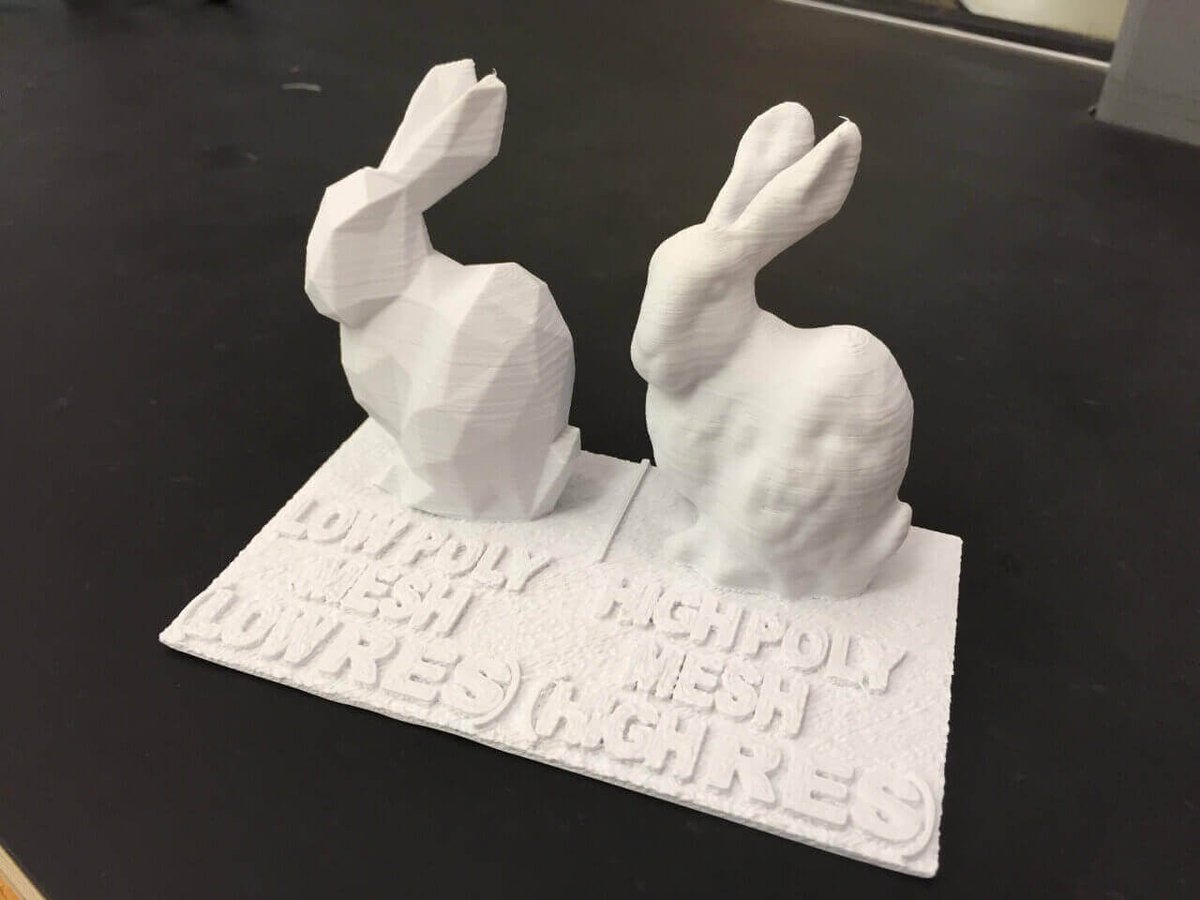
This learning aid is a visual comparison between low and high resolution models. The resolution of the digital model is a separate consideration from physical print settings like layer height. This is specifically about the number of polygons used to form a shape.
The low poly mesh model on the left is a simple design comprised of significantly fewer polygons than the high poly mesh model on the right. The results are obvious, where the surface of the high poly model is smoother and more detailed. The efficiencies of opting for a low-poly model are gained at the design stage, in file-size, and sometimes (but not necessarily always) at the printing stage.
Low poly models are especially popular with the 3D model community, allowing designers to render recognizable objects like Pokemon and Yoda in an artistic way using a elegant arrangement of polygons.
Download the STL files for your own use: poly
What do you think? Any 3D printing concepts that you’d like to see included? Let us know in the comments below!
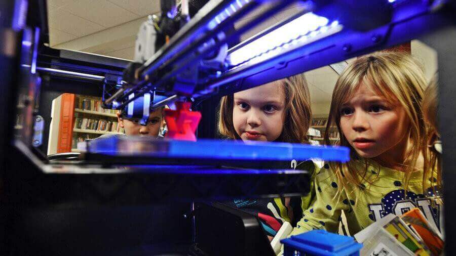
Main Image: NPR
License: The text of "9 Important 3D Printing Concepts Everyone Should Know" by All3DP is licensed under a Creative Commons Attribution 4.0 International License.