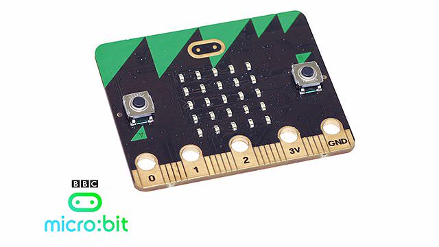
FreeCAD: How to Build a Case for Your BBC micro:bit

This is a step-by-step tutorial on designing a case for your BBC micro:bit computer using the popular FreeCAD software. Newbies welcome!
This tutorial will take you through the process step by step. Plus, you won’t need any previous knowledge of CAD software.
We’ve also made our own STL files available to download at the end of this article. Advanced users who wish to save time are welcome to modify them.
Disclaimer: At the time of writing we did not have a Micro:bit at hand as they are difficult to get outside the UK. We used the measurements provided by the BBC. If you notice any deviations, please send as an e-mail to contact@all3dp.com.
Step 1: Install FreeCAD and set it up
First you will need to download FreeCAD. Look for the right installer for your operating system and install it. Launch FreeCAD after installing.
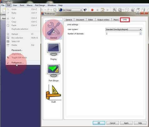
- You will need to change your units to mm. Click on Edit > Preferences and select the Unit tab. Now change your units to Standard mm/kg/s/deg. Confirm by clicking Ok.
- Start a new project by clicking on File > New.
- Save your file by clicking on File > Safe as and save it under any folder you like as Microbit Bottom
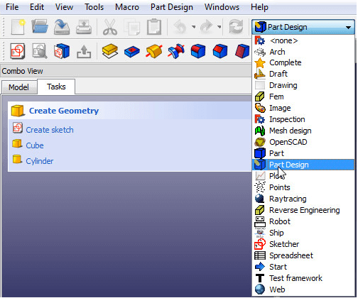
- Change your workbench from Start to Part Design to begin.
Step 2: Build a base for your BBC micro:bit case
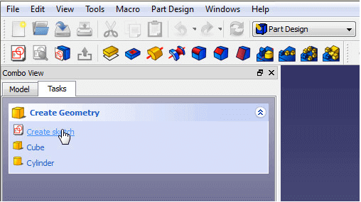
- At first, you need to create a new sketch. Switch in the Combo View window from Model to Tasks and select Create Sketch. Then select XY-Plane and confirm with Ok.
- Now check Show grid, Grid Snap and Auto Constrains. Also set your grid size to 10mm.
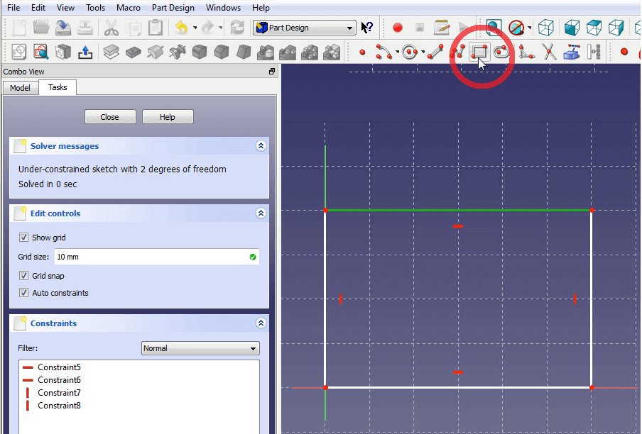
- Create a rectangle by clicking on Create rectangle in your drawing section. Click on the center point to set one edge of your rectangle and place your second one somewhere in the 1. quadrant of the coordinate system. You can move your view around by pressing the middle mouse button or holding down CTRL and dragging the view using the right mouse button.
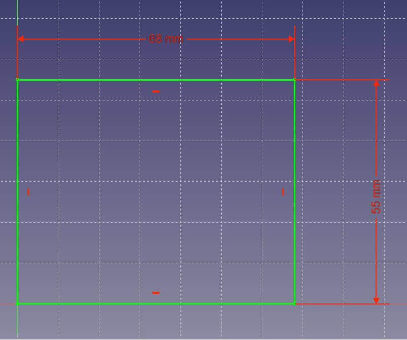
Draw a rectangle starting at the midpoint using the Draw rectangle tool. - Select the bottom line of your rectangle so it shines green. Set its length to 73mm by clicking on the red horizontal length constrain between two points found in your Constrain section.
- Set the vertical component of your rectangle to 55mm by clicking on the red vertical length constraint between two points.
- If your rectangle moves away from the center point, simply left-click the lower left edge of your rectangle and click on the center point (0,0,0) while holding down CTRL. Then click on the red dot in the constrain section to set both points to coincident. Now your entire rectangle should appear in green, which means that it is fully constrained.
- Close the sketch by clicking on Close in the combo view menu to continue.
- Extrude the rectangle by using the Pad tool in the Feature section. Extrude your base to 3mm and uncheck Symmetric to Plane and Reversed. Confirm by clicking Ok. Change the name “Pad” in the model tree to “Base” by clicking onto it once and pressing F2. This will help you to keep an overview of the many more features to come.

Step 3: Build an enclosure for your micro:bit
You will now have to build some walls onto your base to enclose your chip.
- Change the view in the View menu to Axometric view, and click on the top of your base so it shines green.
- Now switch to the Tasks bar and create a new sketch.
- Click on Create a link to external geometry in your drawing section and select the left edge of your base so it shines purple. This will allow you to add a constraint to this edge and connected vertex.
- Add two more external links to the bottom and the top edge of your base.
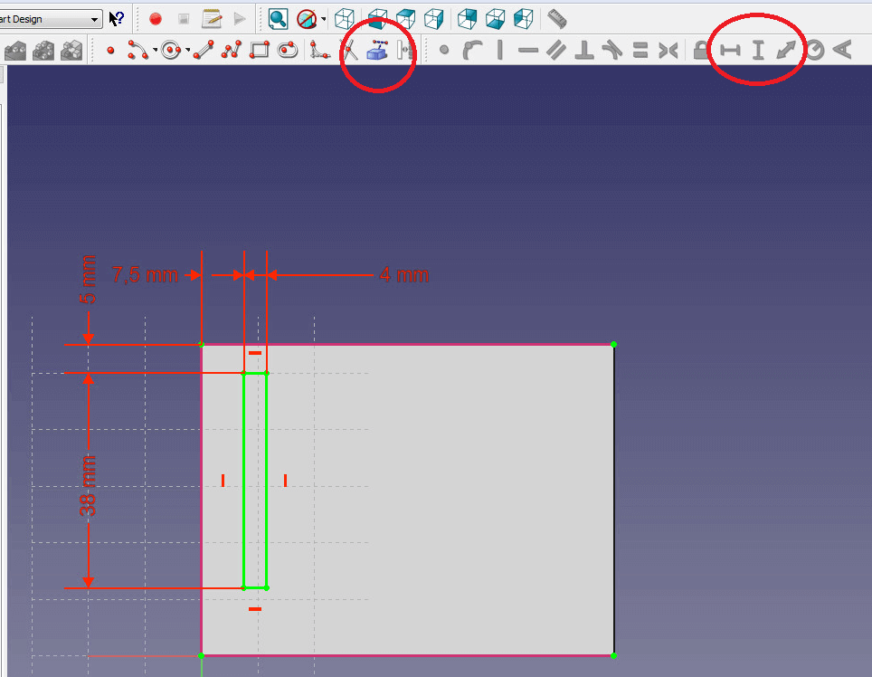
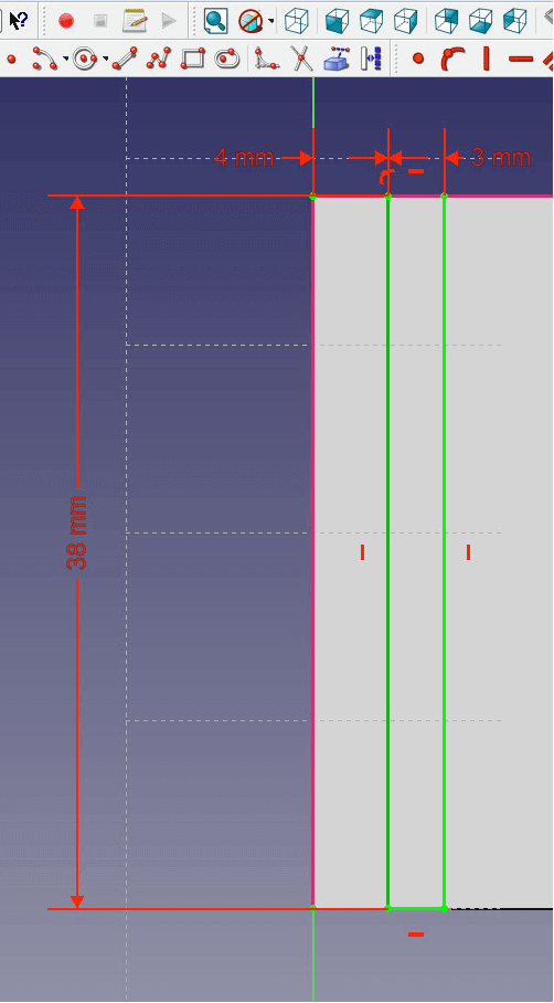
- Create a rectangle on top of your base that does not touch any of the edges.
- Now set the vertical component of the rectangle to 38mm and the horizontal one to 4mm.
- Select the upper left vertex of the base and the upper edge of your rectangle. Set the distance to 5mm by clicking on the red arrow pointing in two directions.
- Set the distance between the upper left vertex and the left edge of your rectangle to 6.75mm.
- Close the sketch and extrude the rectangle to 10mm by using the Pad feature.
- Select the pad in the model tree and rename it to “wall1” by pressing F2.
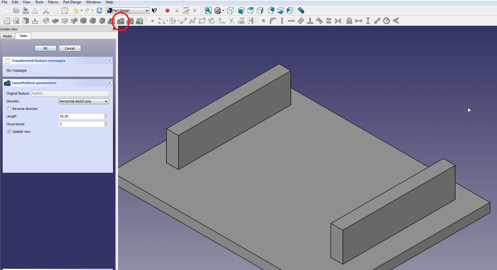
- Use the Linear Pattern feature to copy wall1 to the right by 55.5mm. Set the direction to be the horizontal sketch axis, uncheck Reverse Direction and set Occurrences to 2.
Step 4: Build supports
- Set the top edge of your base, the right bottom edge of your left wall and the left bottom edge of your right wall as an external link. You will have to switch to Axometric view and change the appearance of your model by changing from Flat lines to Wireframes. That way you can see through your model and easily select edges and vertices.
- Now draw a rectangle somewhere in the middle of the two walls.
- Constrain one left and one right vertex of the rectangle to the external links of the walls you created in 1. by using the red fix a point on an object found in the constraint section.
- Now set the distance between an upper vertex of the rectangle and the upper external link of your base to 12mm.
- Also set the distance between the horizontal edges of the rectangle to 5mm. Now your rectangle should be fully defined and shine in green.
- Closesthe sketch and pad the rectangle to 4mm height.
- Use the Linear pattern feature to create a second structure. Change the direction to Vertical Sketch axis, also check Reversed and set the distance to 24.5mm.

Use the linear pattern feature to easily multiply identical objects. - Rename “Pad002” to “Support Back” and the linear pattern to “Support Front” by selecting the object in the model tree and pressing F2.
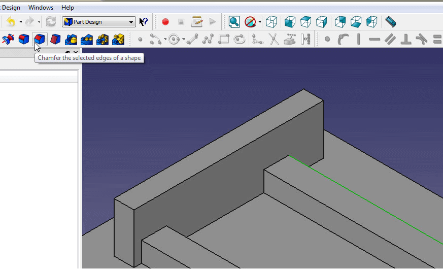
- Click on the edge of your first support then click on create chamfer in the Feature section. Set the chamfer to 2.5mm.
Step 5: Add pins
- Click the top plane of your front support and create a new sketch.
- Set external links to the left walls edge and the bottom edge of your Front Support.
- Now create a circle on top of the front support. You’ll find the Circle tool in the drawing section. Click once to set the Midpoint and a second time for the Radius.
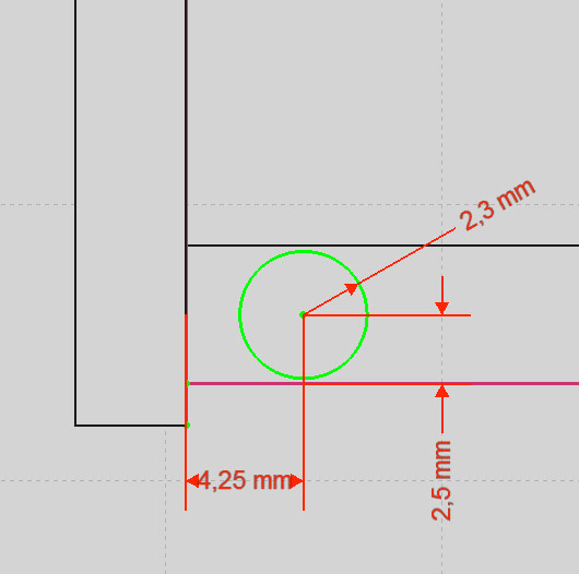
- Change the radius of the circle to 2.3mm by clicking on it and using the Change radius option in the Constrain section.
- Set the distance between the midpoint of the circle and the bottom edge to 2.5mm.
- Also set the distance from the midpoint to the left wall to 4.25mm.
- Now extrude the circle to 8mm height. Rename the object to “Pin” when you are done.
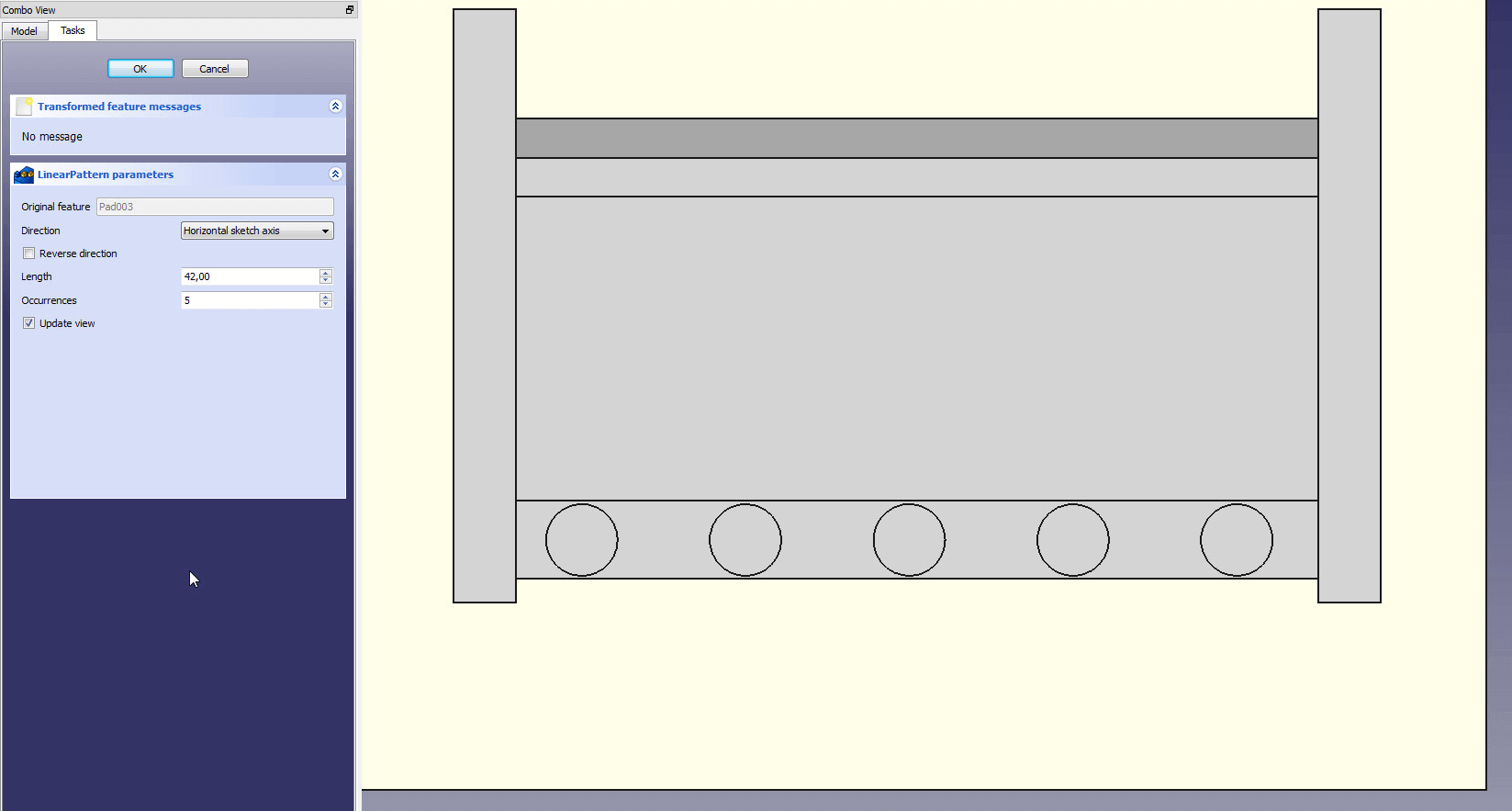
- Use the Linear Pattern feature to create four more pins. The direction is the horizontal sketch axis, the length is 42mm, uncheck Reversed direction and set Occurrences to 5. Change the “Linear Pattern” to “Pins” when you are done.
Step 6: Create holes for the buttons
- Select the top plane of your base and create a new sketch.
- Set the top edge and the right edge of your left wall as an external reference.
- Draw a rectangle on the upper part of your base.
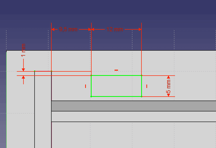
- Set the horizontal distance to 12mm and the vertical distance to 5mm.
- Now set the constrains for the distance to the top and the right edge. Select the left vertical component of the rectangle and a right vertex of the right wall. Now set the distance to 9.5mm as you did in step 3.6.
- Also set the distance between the top edge of the rectangle and a top vertex of the wall to 1mm. The rectangle should be fully constrained now.
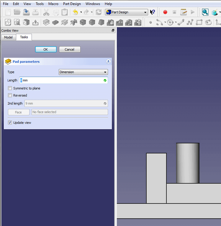
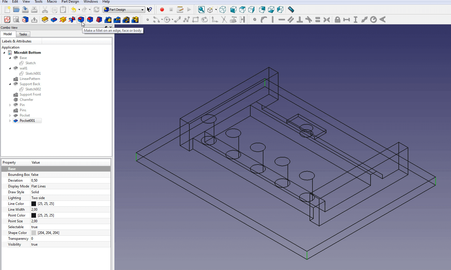
- Exit the sketch and use the Pocket tool found in the Feature section to cut a rectangular hole. Set Type to Dimension, Length to 1mm and uncheck the boxes below.
- Create a new sketch inside the sag and the left and upper edge as external reference point.
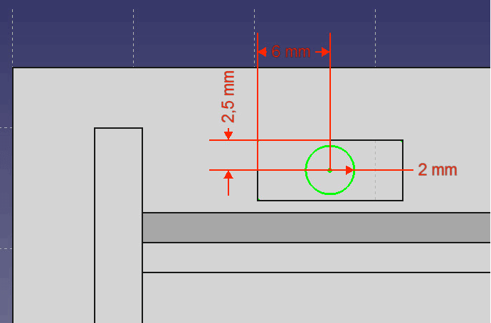
- Draw a circle in the middle of the sag.
- Set the radius to 2mm using the Constraint tool. Also set the distance to the left edge to 6mm and to the top edge to 2.5mm.
- Exit the sketch and use the Pocket feature to cut through the base. To do so, set Type to through all.
Step 7: Finish the bottom part
The bottom part of your case is finished, but if you want to, you can smoothen the edges in this step.
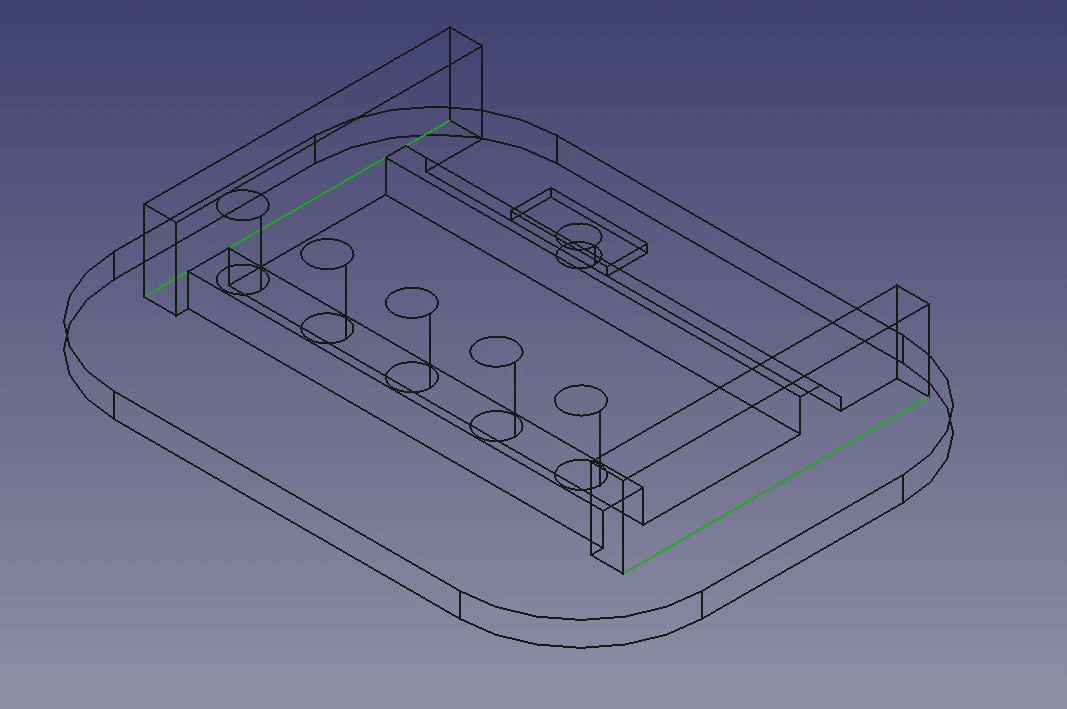
- Turn the Draw style to Wireframe and select the corner edges of the base.
- Use the Fillet tool found in the Feature section to deburr it a little. See what radius suits you best. We recommend 15mm. Be careful not to undermine the walls!
- Now select the outer bottom edges of the walls and also use the Fillet feature with a radius of 2.5mm. This will give the structure some support.
- Set your view to Bottom view and select one part of the cut you did for the button. Use the Chamfer right next to the Fillet tool and set the size to 1.5mm.
You are done with your bottom part now!
Step 8: Build the cover for the micro:bit case
You will need a cover for your micro:bit, so let’s build one.
- Start a new project.
- Create a new sketch on the XY-Plane.
- Draw a rectangle starting at the center point and set its vertical to 38mm and the horizontal component to 59.5mm.
- Use the Pad feature to extrude the sketch to 3mm. Rename the object to “Top“.
- Create a new sketch on the top part. Set the left and top edge of the top part as an external reference.
- Draw a rectangle and size it to 38mm vertically and 3mm horizontally.
- Constrain the distance to the left edge to 4mm and make one top vertex coincident to the top edge of coincident to the top edge by using the Fix a point to an object constraint.
- Extrude the rectangle to 3mm height and rename it “Top Wall“.
- Pattern the wall over the horizontal sketch axis up to 48.5mm. Set the Occurrences to 2.
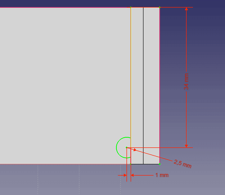
- Create a new sketch between the walls. Set the top and right edge of the top as an external link as well as the left edge of the right wall.
- Draw a circle and set the radius of the circle to 2.5mm, the distance to the left edge of the right wall to 1mm and to the top edge to 34mm.
- Use the Pocket feature to cut out the circle. Set the type to Through all and check Symmetric to sketch axis. Rename it to “Hole”.
- Now use the Linear pattern feature to copy the hole. Set the direction to Horizontal sketch axis, check Reverse, set the length to 42mm and Occurrences to 5.
- Create a new sketch on the top of the right wall. Set the left edge of and the circle intersecting with it as external reference.
- Now draw a rectangle. Set the left vertical component of the rectangle tangential to the circle and the horizontal ones as well.

Use the Fix a point to an object tool to make a line tangential to a circle. - Use the Pocket feature to cut out 3mm.
- Create a new sketch between the walls and set the top edge of the top part and the right edge of the left wall as external reference.
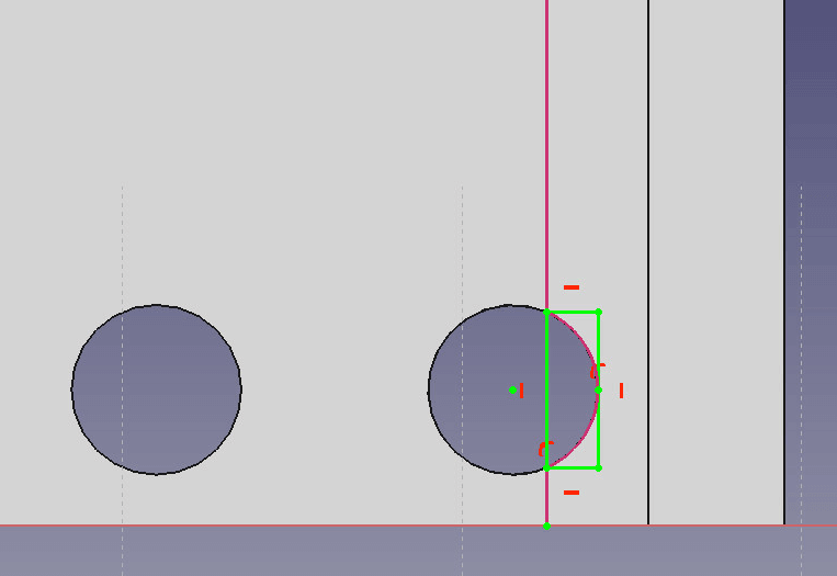
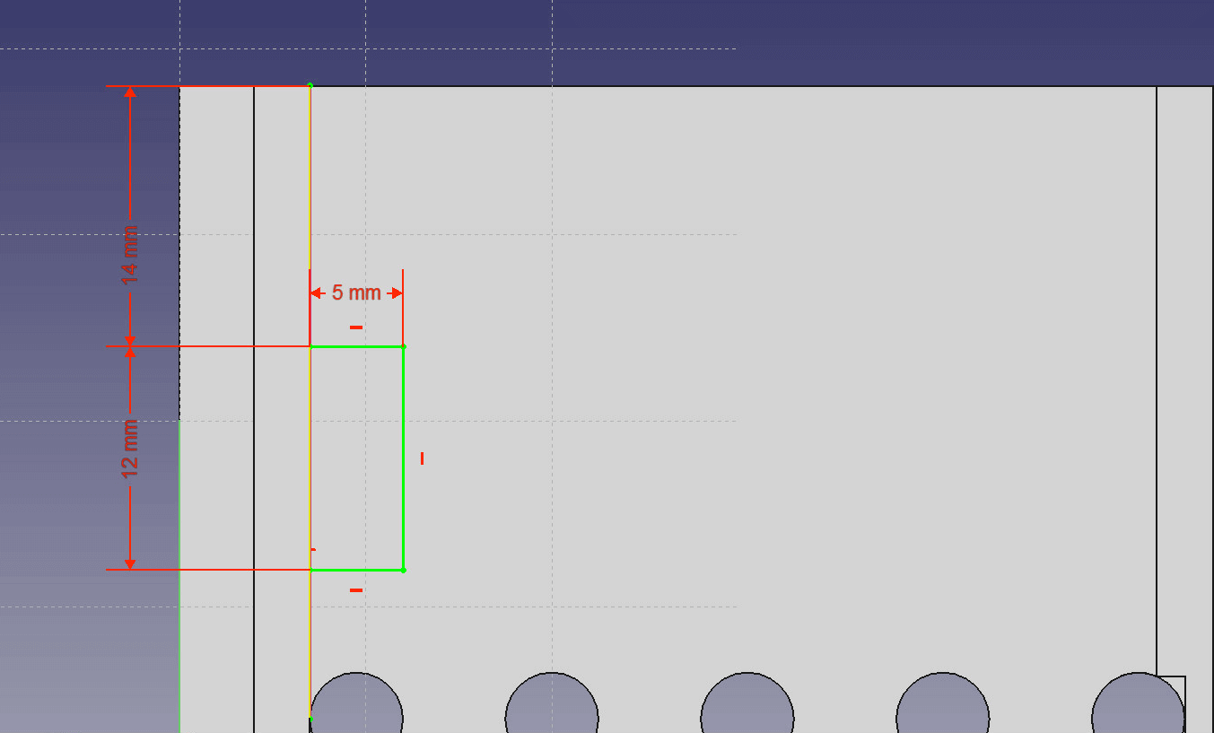
- Draw a rectangle coincident to the left wall, a distance of 14mm to the top edge and with 12mm height and 5mm length.
- Use the Pocket feature to cut 1mm deep. Rename the cut to “Button1”.
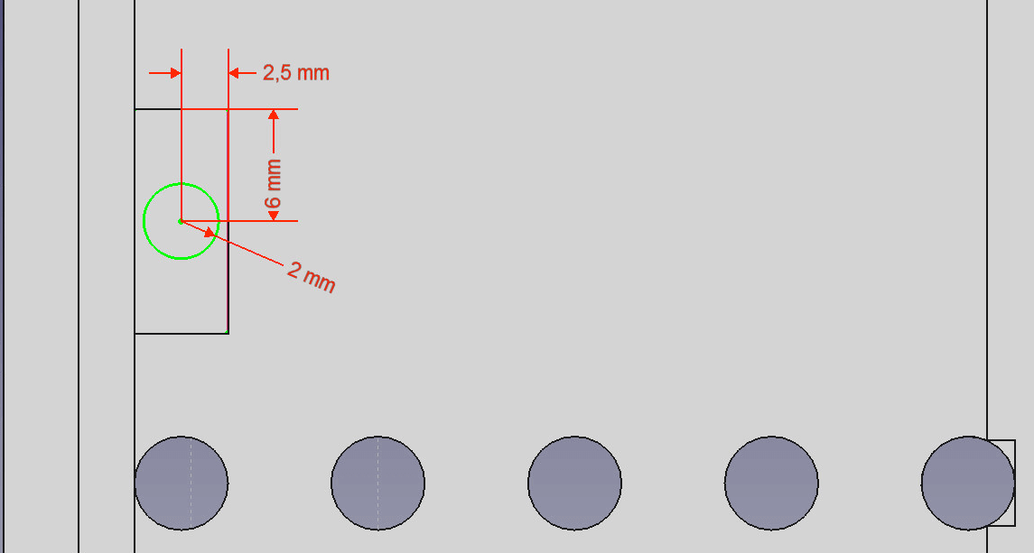
- Create a new sketch in the sag and set the right and upper edge as external reference.
- Draw a circle and set the radius to 2mm. Set the distance to the left edge of 2.5mm and the top with 6mm.
- Use the Pocket feature to cut a hole through all. Rename the cut to “Button2”.
- Repeat 17.-22. on the right side so the holes for the buttons are symmetrical.
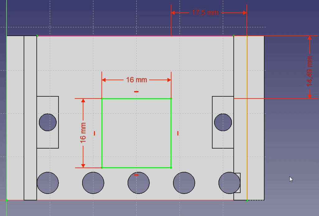
- Create another sketch between the walls and set the right edge of the right wall and the top edge as an external reference.
- Draw a rectangle and size it 16mm x 16mm. Set the distance to right wall to 17.5mm and to the top to 14.49mm.
- Use the Pocket feature to cut through all.
Step 9: Design the buttons
- Start a new project and create a new sketch.
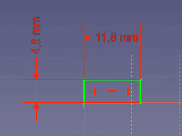
- Draw a rectangle and set the vertical component to 11.8mm and the horizontal to 4.8mm.
- Extrude it to 1.5mm height.
- Create a new sketch on top of the box and set the left and top edge of the box as external reference.
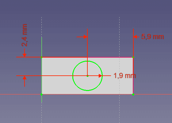
- Now draw a circle. Set the radius to 1.9mm, the distance to vertical edge to 5.9mm and to horizontal edge to 2.4mm.
- Extrude the circle to 3mm height.
- Create a fillet on the top rim with the radius of 1mm.
Step 10: Export as an .STL file for 3D printing
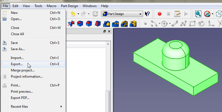
- To export a model from FreeCAD to the .STL file format, simply click on the last feature in the model tree of an bbject so the object you want to export turns green.
- Then go to File > Export and set file type to Mesh formats.
Download the STL files from our workshop
Download the STL files files from our workshop and use them at your convenience.
Please, remember: We did not have a Micro:bit when we designed the case in FreeCAD. If there is anything wrong with our STL files, please inform us – so we can correct the files.
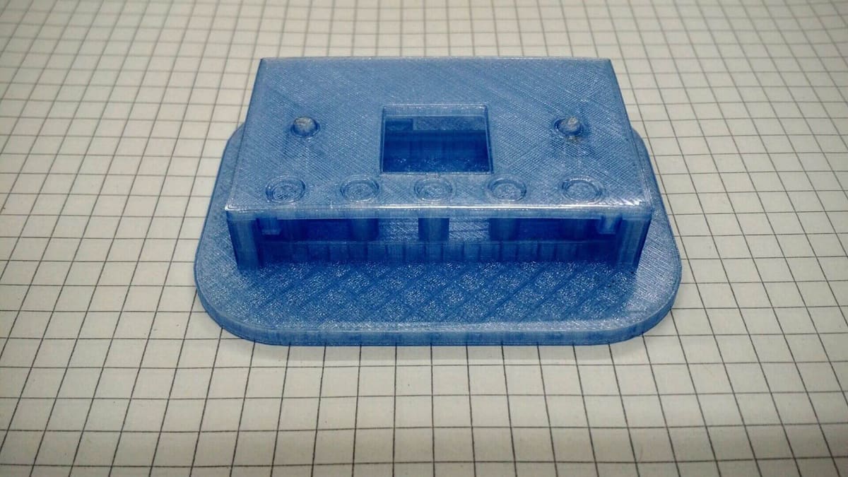
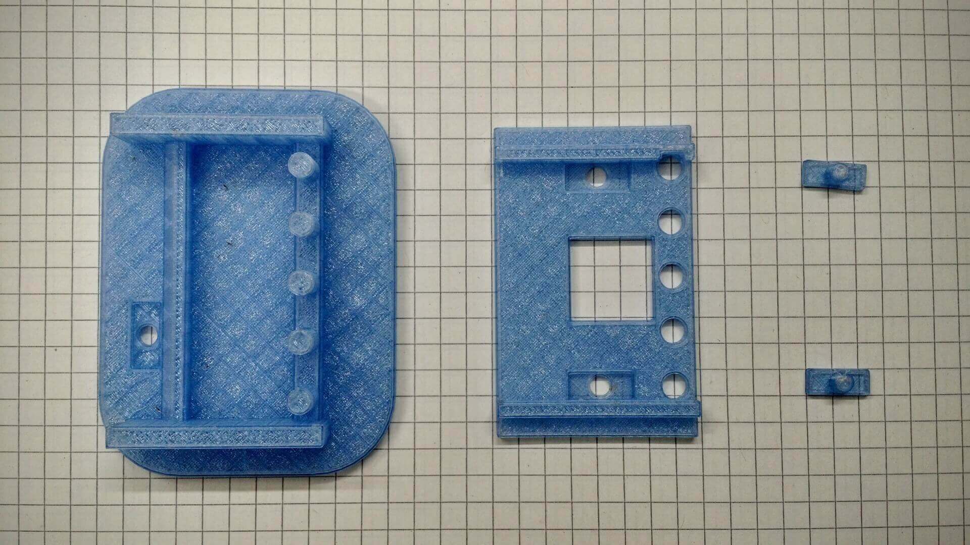
Step 11: Print the micro:bit case
Now you only have to print each piece plus the buttons three times, and you have your own micro:bit case
If you do not have a 3D printer, you can send the STL files to a printing service and have them printed.
Use All3DP’s price comparison service to find the best price for your case and directly order from the printing service of your choice.
License: The text of "FreeCAD: How to Build a Case for Your BBC micro:bit" by All3DP is licensed under a Creative Commons Attribution 4.0 International License.