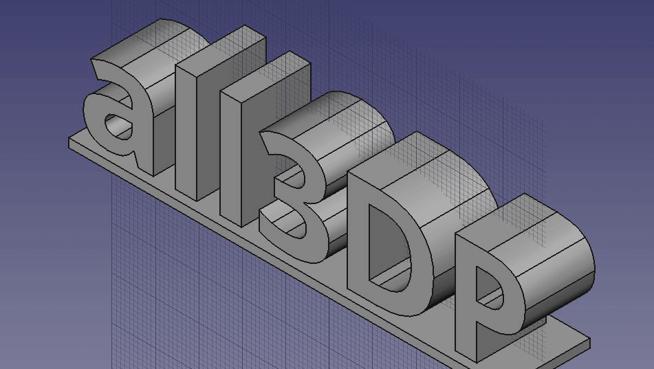
How to 3D Print Letters or Text using FreeCAD

Have you ever wanted to see your name printed in 3D? Learn how to 3D print letters or text using FreeCAD in just four easy steps.
Welcome to ALL3DP’s tutorial on 3D printing letters or text with FreeCAD. You won’t need any previous knowledge on working with a CAD program; all the instructions you need are detailed below.
SPLIT_DOM_HEREFreeCAD Text – Step 1: Install FreeCAD
First things first, you need to download and install FreeCAD. You can download it from their website https://www.freecadweb.org/ for free.
For this project you will also need a font. You can either download one from the internet, or use one already installed in your system. The required file formats are either .ttf, .ptf, or .otf. Place the selected font into a folder on your disk named CADFont.
FreeCAD Text – Step 2: Create a Base
To connect the different letters and to support them you will have to create a base.
1. Create a new project. To do so open FreeCAD and click on File > New.
2. Change your Workbench from Start to Part Design. This will enable the option Create Sketch under the Task slide in the combo view window.
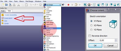
3. Click on Create Sketch to open a new window. Select the orientation to sketch on.
4. Now choose the XY-Plane, uncheck reverse direction and zero the offset. In this window the cube on the right will show you the selected plane. The Reverse Direction option will switch to the opposite plane. With the option Offset you can change the height of the plane. Press OK to proceed.
5. You can see new options in the Tasks tab. Here we can change the Grids properties. Check all the grid options and set the Grid size to 10mm. Unchecking Show grid will hide the grid and Grid size will vary the spacing of the grid. Selecting Grid Snap will automatically snap a point to the closest crossing.
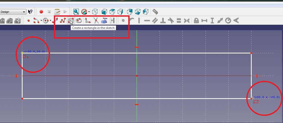
6. Select the sketch tool Create a Rectangle. When you move your cursor over the coordinate system you can see the current coordinates right next to your cursor. Click in the IV section of the coordinate system on the point -50.0, 10.0. You can also notice how the points snap to the grid which lets you work more precise. Make your rectangle 100.0 x -20.0 wide. FreeCAD automatically sets constrains to your sketch as you see in the Constrains window on the left. Click on Close to exit the Sketch.
7. Select the Model tab in the combo view and click on S. By pressing F2 you can change the name of an entity. Change the name from Sketch to Base.
8. Click on Base again, switch to the Tasks tab in the combo view and click on Pad.
9. Set Length in the Pad Parameters window to 2mm and uncheck Symmetric to plane and Reversed. Press OK to create the pad. To see the entire object press 0 (zero) on your keyboard. The view changes to axometric. You can also change the views by right clicking on the drawing window and selecting standard views.
FreeCAD Text – Step 3: Create 3D Letters or Text
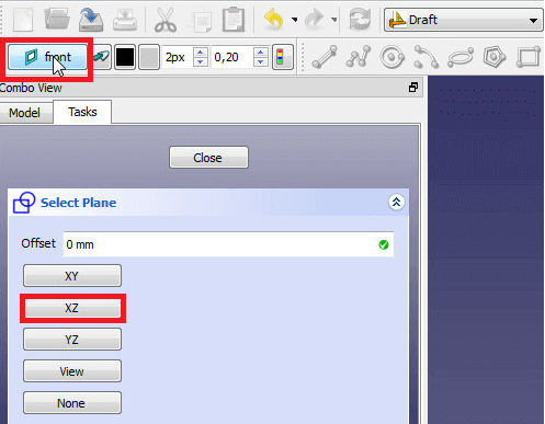
1. Switch your Workbench to Draft and change your draft plane. To change the draft plane, click on Set/unset working plane and select XZ-Plane.
2. Change your view to Front view. Then click the S icon to convert the string into a shape. Now set Local X in the shape string window to -50.0; set Local Y to 8.0 and Local Z to 2.0. These variables describe the position of the starting point. Press Enter to continue.
3. Now type your text (name, signature, whatever) in the string box. Confirm by pressing Enter.
4. Set the height to 30.00mm and press enter to continue. Set Tracking to 0.00 and press enter. This will determine the path of the shape.
5. You now have to select the full path of the font file. Click on the … box and select the font file on your desktop. When you switch to axometric view you will see the 2D shape of your text.
6. If your lettering does not fit on the base either change the Local X variable or extend the base.
Please note
Unfortunately, you won’t be able to use small “i”, accented letters, or umlauts such as “ä” or “Ä” – unless you decide to add a support structure that’s small but strong enough. Otherwise the dot on the “i” or on the umlaut will be lost as its being printed.
FreeCAD Text – Step 4: Extrude
To turn the 2D shape into a letters to 3D print, simply switch your workbench back to Part Design, select ShapeString in the Modell section and click on Pad a selected sketch. Set the length of your pad to 16mm.
That’s it. Now your 3D text in FreeCAD is ready to print.

Learn more
If you want to learn more about using FreeCAD, check our tutorial: FreeCAD Tutorial: 3D Printing for Beginners.
License: The text of "How to 3D Print Letters or Text using FreeCAD" by All3DP is licensed under a Creative Commons Attribution 4.0 International License.